S J
100+ Head-Fier
- Joined
- Dec 7, 2008
- Posts
- 288
- Likes
- 12
Hi there, I'm reposting this guide with the permission of the original writer, as he was made to feel that leaving the original guide posted was inappropriate (that's all I'm going to say about that). Anyway, I managed to recover the original post from Google Cache in its entirety; there may be some formatting errors and some links may not work initially, but I'll get it fixed up in a bit. If you find some that don't work, or it looks like a picture is missing, please let me know. Once again, this guide is not my work; everything below this point is a copy and paste job.
------------------------------------------------------
Credit to 14124all @ Sandisk's forum who first described and built fuze's diyLOD (read here) and waino from the same forum who took his time to do the measurement. This guide is merely a more graphical approach to re-describe the same process of building the diyLOD.
[size=large][size=medium]Prelude:[/size][/size]
There are some discussions on whether the line-out signal from the dock connector is true line-out or not. Sansafix @ Sandisk's forum, who is Sandisk's tech support, has confirmed that it is indeed line-out signal, not headphone-out at 100%. The main benefit of using the line-out signal, from my point of view, is its better SNR compared to Fuze's headphone-out (which makes its LO better for amping). When comparing Fuze's headphone-out and line-out, I do find them to sound differently in some subtle ways. In comparison (flat EQ), line-out (via diyLOD v1) sounds more neutral and spacious. Fine detail and image (soundstage) tend to jump out more easily. LO does seem to have a darker, quieter background as well. Headphone-out on the other hand sounds more mid-focus and energetic. It almost makes me think that HO is somehow EQ'ed, or may be coloration is the correct word for it. Since Fuze's headphone-out already sounds fantastic by its own, it is hard to say that line-out + amp are a major improvement over headphone-out + amp. IMO, it really boils down to personal taste and how one perceives what is the most natural sound. [EDIT] If you want to read more about the tech side of the story, it is at the end of post #2.
One thing you should note is, due to how Fuze's EQ is applied to music (which is in DSP / CPU, before the music reaches DAC), it will still affect the sound in line-out mode. If you insist on getting a 'pure' line-out signal, you should turn EQ off when you are using the diyLOD.
To ensure you are getting the best out of the diyLOD, you'll need to update your Fuze firmware to the latest version!!! The latest firmware are 01.01.22 (for hardware rev.1) and 02.01.17 (for hardware rev.2). You can find more detail on how to update your Fuze here. [UPDATE] The latest firmware is now 0X.02.26, found here.
What you don't need:
Cheap replacement cable from eBay - most of them only have the first 6 pins needed for sync and charge. You will not be able to modify it since pin #7, 22, 27, and 28 are not there. You can, however, use it as you sync and charge cable after you modified the original cable (if you are not using Ridax's connector).
As always, this is a Do-It-At-Your-Own-Risk modification.
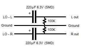
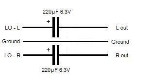
[size=medium]*[/size]Not sure which version of diyLOD you should use? In short, use diyLOD v1 if your amp has input DC filters (i.e. capacitive coupling / AC coupling). Use diyLOD v2 if your amp doesn't have them (or when you can't be sure). See the 2nd to last section on post #2 for more detail.
[size=large][diyLOD v1][/size]
- original sync and charge cable mod
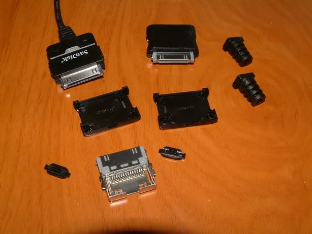
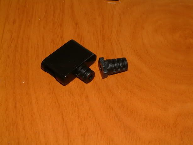
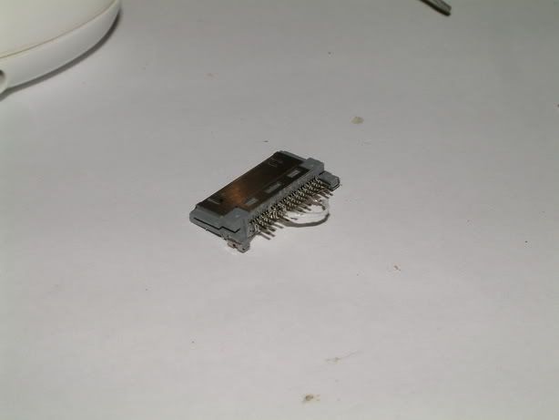
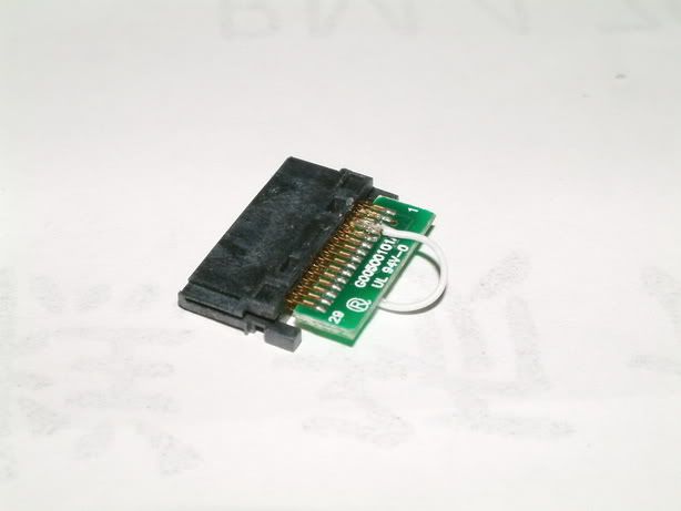
[size=medium]1. Taking apart the connector.[/size]
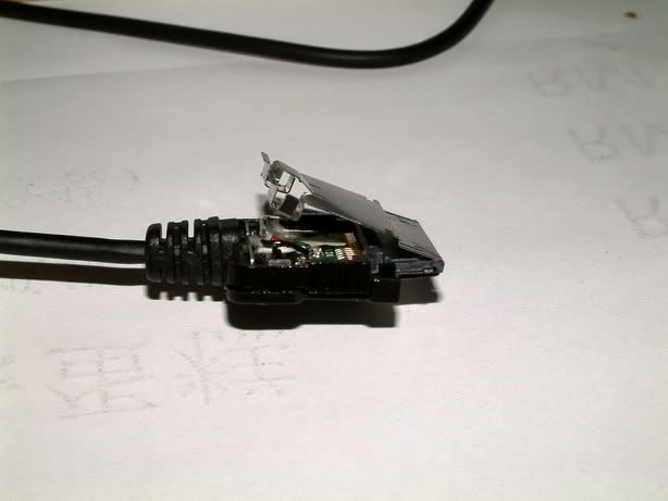
The connector is held together mainly by two hooks at the cable end of the connector (where the two holes on each side are). Those hooks shaped differently which make them a lot more difficult to take apart.

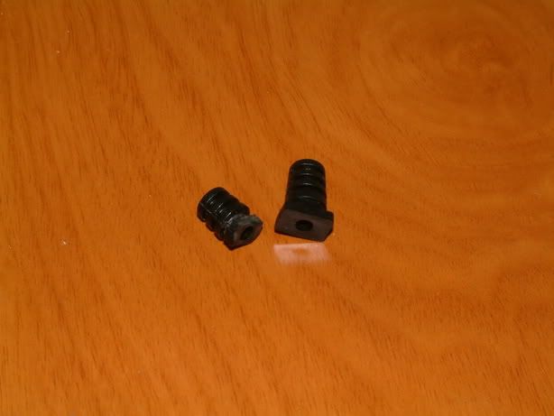
I use the small flathead screwdriver for repairing watches to pry open the bottom side of the connector - first I force the screwdriver underneath where the strain relief goes into the connector, than I pry on each side (black arrow) till it is loose - be careful on this part as you don't want to destroy the housing before you even began the mod.
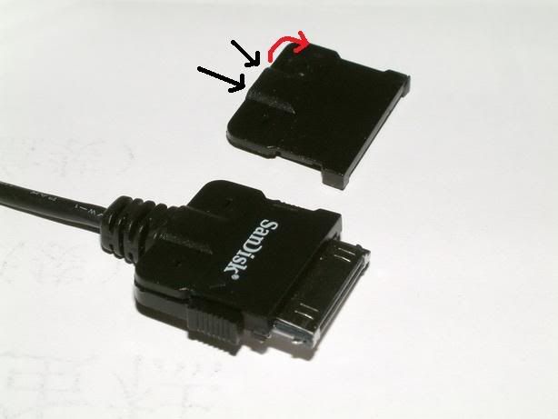
Red circles mark the hooks and green arrow is where the screwdriver goes in / force applied
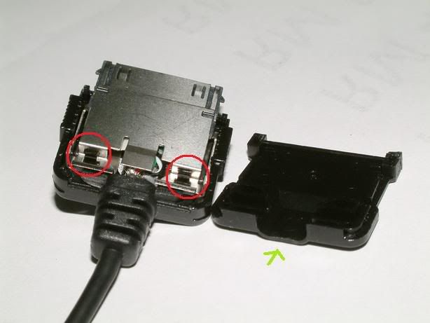
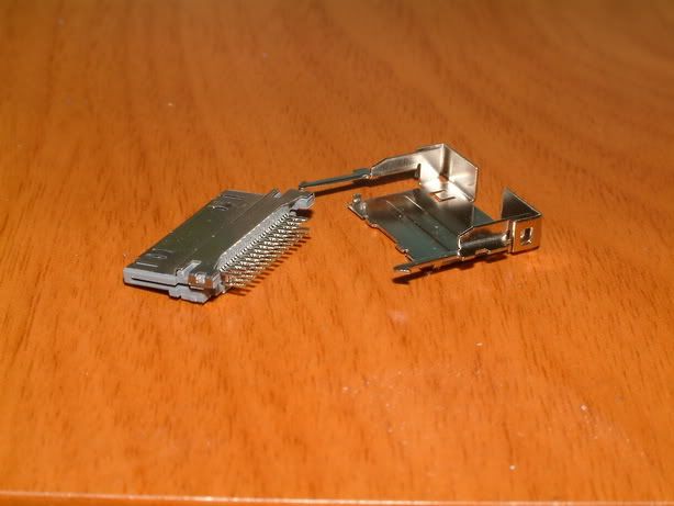
You can lift this part of the metal shielding once the whole connector is out of the plastic housing. Don't bend the metal too much or it will break.
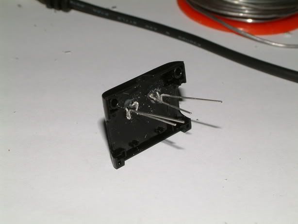
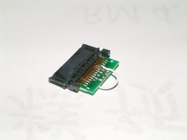
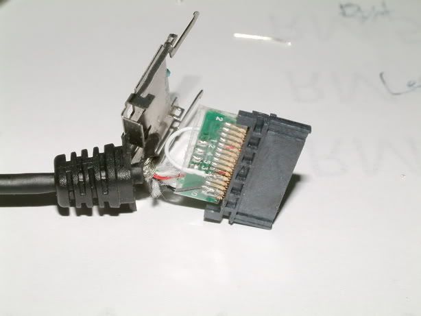
The complete disassembly of the connector. Note: you are looking at the bottom side of the connector (pin #2, 4, 6, ... , 30)
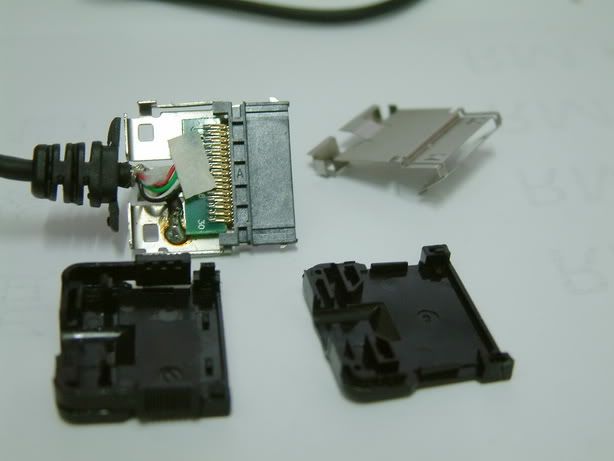
The bottom, where the USB connections are wired.
The top, same side as the Sandisk logo is.
[size=medium]2. Rewiring.[/size]
I de-solder all the USB wires first as I like it that way (except the USB shielding that connect to the connector shielding). There is no reason to pick one color wire over the other for a particular channel - you can pick what ever way you want to solder them, just be sure to remember to solder them in the correct way when you terminate them at the other end with mini jack. It is also a good time to cut the USB cable to your desired length. I left about 4 inches of USB cable attached from the end of connector strain relief - which is about 3 inches left after I put on the mini jack. You might want to leave a bit more depends on your own preference and future usage.
Here is a sum up of what was / is during the rewiring process:
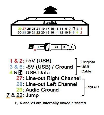
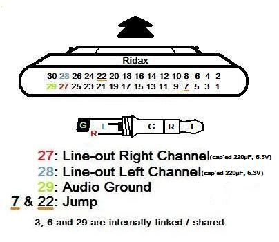
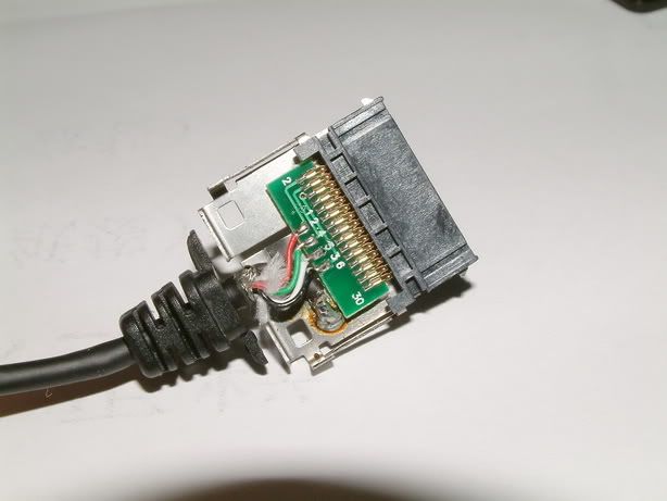
First, you want to jump pin #7 and pin #22. They are located on two different side. I jumped them with the leftover cable on the original USB cable. The reason for jumping the two pins is because it requires a small voltage (1V ~3V) on pin #7 to activate the LO mode, and it just so happens Fuze's pin #22 has 3V supply that can be utilized in this situation. Note that whether other Sandisk player has the same 3V on pin #22 is yet to know. Until we do know about it, you shouldn't use the diyLOD on any other Sandisk player besides Fuze.
Pin #7:
Pin #22: (I marked #10 and #20 red for better recognition)
Once you jump the pins, should check both the connection b/w the pins with multimeter, as well as the neighboring pins (i.e. pin #5 and #9, #20 and #24) to make sure nothing short! Measure every time you finish soldering a pin!!!
A quick test: To see whether you can activate LO at time point, start playing a songs on Fuze and listen to it, than insert the jumped connector in and you will notice the music is silenced (on headphone) but continue to play on the player. You will also notice the scroll wheel no longer able to control the volume. Remove the connector and everything should go back to normal. Note: Your Fuze must be in the latest firmware to perform this test.
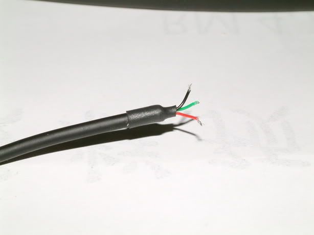
I pick red cable as my right channel, black as my left channel, as green as my audio ground. Note that you should also be able to use Pin #3 and 6 (USB ground) as your audio ground as well. Note: be careful on the cable length b/w the strain relief and the pins - you don't want it to come short when you try to put them back together. If you are not sure, extend the cable by wiring an extra length of wire and insulate it properly (you don't want them to short either!)
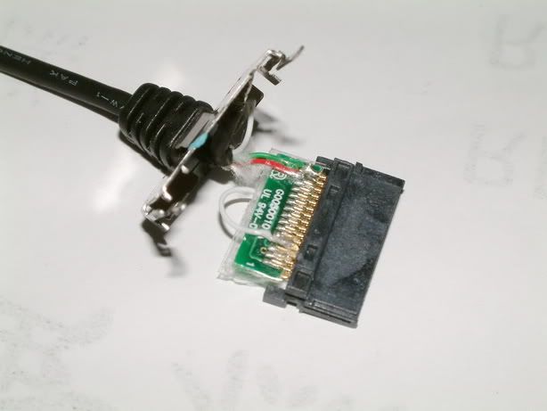
Since I didn't use the USB shielding for anything, I insulated it as well.
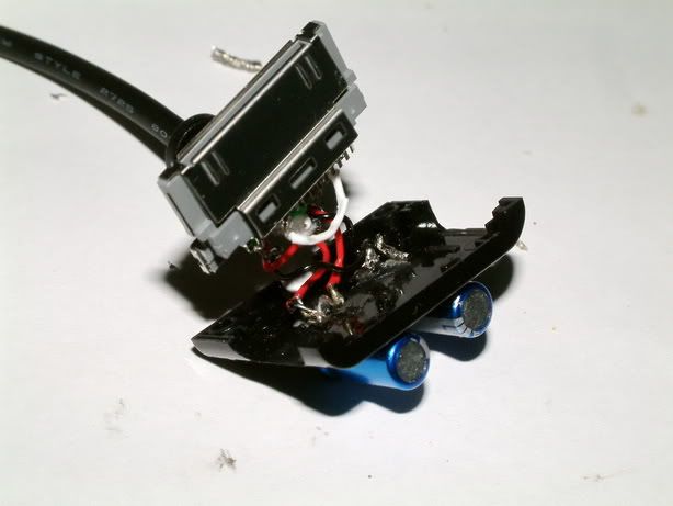
[size=medium]3. Reassembly[/size]
Remember to put some tape over the PCB to avoid short circuit,
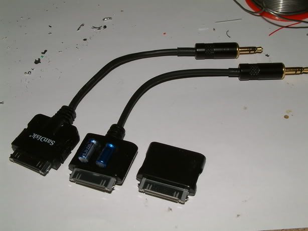
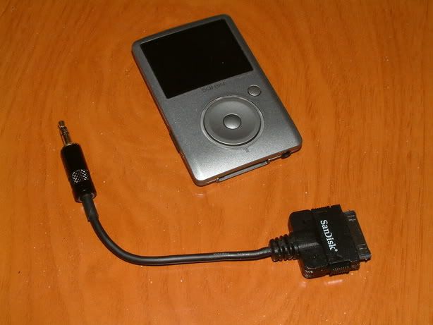
Terminate the other end with a mini jack and voila, you have yourself a diyLOD!
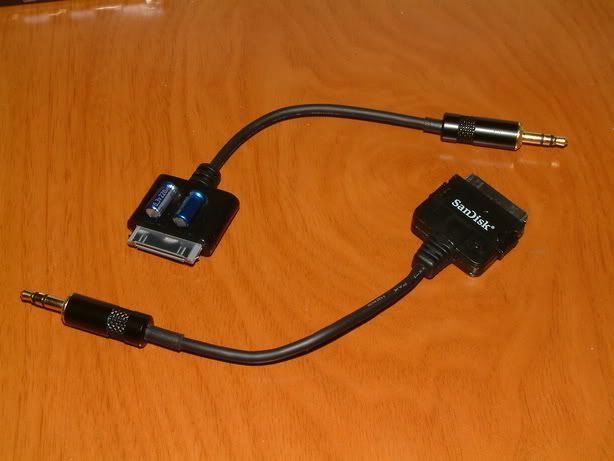
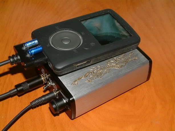
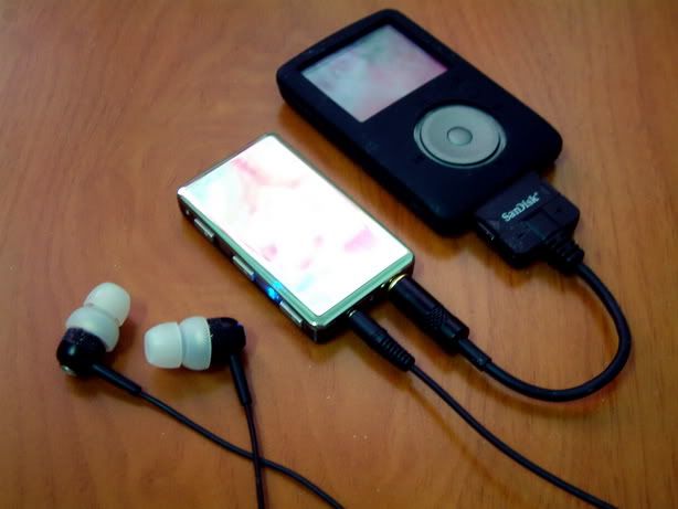
Fuze - diyLOD - FiiO E5 - Head-Direct RE0
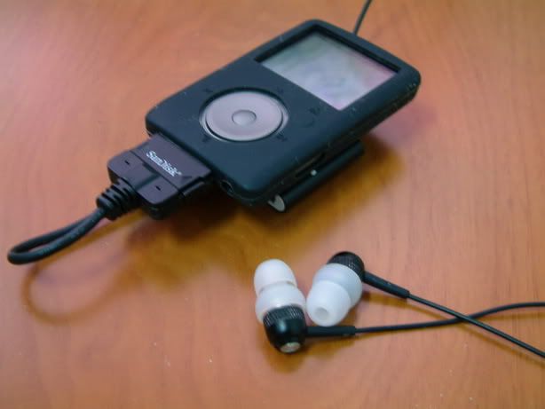
Fuze - diyLOD - iBasso T4 - Head-Direct RE0
Continue to next post...
-------------------------------------------------
Again, everything above that line is not my work! See the notes at the beginning of this post for an explanation. I did a quick scan of these posts to make sure nothing was missing and I'm pretty sure I tried all the links, but if it looks like an image is missing (or is in the wrong place) or a link is bad, please let me know. Cheers!
The original thread is still available here and contains some additional user-posted images and discussion about the LOD, but please post comments in this thread, linking back to the old one if necessary.
------------------------------------------------------
Credit to 14124all @ Sandisk's forum who first described and built fuze's diyLOD (read here) and waino from the same forum who took his time to do the measurement. This guide is merely a more graphical approach to re-describe the same process of building the diyLOD.
[size=large][size=medium]Prelude:[/size][/size]
There are some discussions on whether the line-out signal from the dock connector is true line-out or not. Sansafix @ Sandisk's forum, who is Sandisk's tech support, has confirmed that it is indeed line-out signal, not headphone-out at 100%. The main benefit of using the line-out signal, from my point of view, is its better SNR compared to Fuze's headphone-out (which makes its LO better for amping). When comparing Fuze's headphone-out and line-out, I do find them to sound differently in some subtle ways. In comparison (flat EQ), line-out (via diyLOD v1) sounds more neutral and spacious. Fine detail and image (soundstage) tend to jump out more easily. LO does seem to have a darker, quieter background as well. Headphone-out on the other hand sounds more mid-focus and energetic. It almost makes me think that HO is somehow EQ'ed, or may be coloration is the correct word for it. Since Fuze's headphone-out already sounds fantastic by its own, it is hard to say that line-out + amp are a major improvement over headphone-out + amp. IMO, it really boils down to personal taste and how one perceives what is the most natural sound. [EDIT] If you want to read more about the tech side of the story, it is at the end of post #2.
One thing you should note is, due to how Fuze's EQ is applied to music (which is in DSP / CPU, before the music reaches DAC), it will still affect the sound in line-out mode. If you insist on getting a 'pure' line-out signal, you should turn EQ off when you are using the diyLOD.
To ensure you are getting the best out of the diyLOD, you'll need to update your Fuze firmware to the latest version!!! The latest firmware are 01.01.22 (for hardware rev.1) and 02.01.17 (for hardware rev.2). You can find more detail on how to update your Fuze here. [UPDATE] The latest firmware is now 0X.02.26, found here.
Note 1: There are two types of Fuze connectors: the snap-on (+ half shielded) and the glue-on (+ full shielded) type. Ridax sells both types, and Qables only sells glue-on type. To make diyLOD v2, you should choose snap-on type. For diyLOD v1, both types can be used (glue-on type is slightly smaller). Note that the Sansa (Fuze) connector is also known as Creative Zen connector.What you will need:
1 x original sync and charge cable for diyLOD v1.
1 x Fuze's 30 pins connector (*see note 1 below for detail) for diyLOD v2. You can use this connector for v1 as well but please pay attention to pins' orientation.
1 x mini plug
1 x soldering iron, small tip (and some solder of course)
1 x Multimeter
1 x Super glue (diyLOD v2)
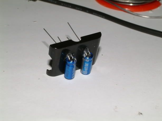
2 x Capacitors (diyLOD v2, please read v2 guide for choosing the right caps))
Optional: cables (depends on how fancy you want it to be), Ridax strain relief (diyLOD v2)
What you don't need:
Cheap replacement cable from eBay - most of them only have the first 6 pins needed for sync and charge. You will not be able to modify it since pin #7, 22, 27, and 28 are not there. You can, however, use it as you sync and charge cable after you modified the original cable (if you are not using Ridax's connector).
As always, this is a Do-It-At-Your-Own-Risk modification.
[size=medium]*[/size]Not sure which version of diyLOD you should use? In short, use diyLOD v1 if your amp has input DC filters (i.e. capacitive coupling / AC coupling). Use diyLOD v2 if your amp doesn't have them (or when you can't be sure). See the 2nd to last section on post #2 for more detail.
[size=large][diyLOD v1][/size]
- original sync and charge cable mod
[size=medium]1. Taking apart the connector.[/size]
The connector is held together mainly by two hooks at the cable end of the connector (where the two holes on each side are). Those hooks shaped differently which make them a lot more difficult to take apart.
I use the small flathead screwdriver for repairing watches to pry open the bottom side of the connector - first I force the screwdriver underneath where the strain relief goes into the connector, than I pry on each side (black arrow) till it is loose - be careful on this part as you don't want to destroy the housing before you even began the mod.
Red circles mark the hooks and green arrow is where the screwdriver goes in / force applied
You can lift this part of the metal shielding once the whole connector is out of the plastic housing. Don't bend the metal too much or it will break.
The complete disassembly of the connector. Note: you are looking at the bottom side of the connector (pin #2, 4, 6, ... , 30)
The bottom, where the USB connections are wired.
The top, same side as the Sandisk logo is.
[size=medium]2. Rewiring.[/size]
I de-solder all the USB wires first as I like it that way (except the USB shielding that connect to the connector shielding). There is no reason to pick one color wire over the other for a particular channel - you can pick what ever way you want to solder them, just be sure to remember to solder them in the correct way when you terminate them at the other end with mini jack. It is also a good time to cut the USB cable to your desired length. I left about 4 inches of USB cable attached from the end of connector strain relief - which is about 3 inches left after I put on the mini jack. You might want to leave a bit more depends on your own preference and future usage.
Here is a sum up of what was / is during the rewiring process:
First, you want to jump pin #7 and pin #22. They are located on two different side. I jumped them with the leftover cable on the original USB cable. The reason for jumping the two pins is because it requires a small voltage (1V ~3V) on pin #7 to activate the LO mode, and it just so happens Fuze's pin #22 has 3V supply that can be utilized in this situation. Note that whether other Sandisk player has the same 3V on pin #22 is yet to know. Until we do know about it, you shouldn't use the diyLOD on any other Sandisk player besides Fuze.
Pin #7:
Pin #22: (I marked #10 and #20 red for better recognition)
Once you jump the pins, should check both the connection b/w the pins with multimeter, as well as the neighboring pins (i.e. pin #5 and #9, #20 and #24) to make sure nothing short! Measure every time you finish soldering a pin!!!
A quick test: To see whether you can activate LO at time point, start playing a songs on Fuze and listen to it, than insert the jumped connector in and you will notice the music is silenced (on headphone) but continue to play on the player. You will also notice the scroll wheel no longer able to control the volume. Remove the connector and everything should go back to normal. Note: Your Fuze must be in the latest firmware to perform this test.
I pick red cable as my right channel, black as my left channel, as green as my audio ground. Note that you should also be able to use Pin #3 and 6 (USB ground) as your audio ground as well. Note: be careful on the cable length b/w the strain relief and the pins - you don't want it to come short when you try to put them back together. If you are not sure, extend the cable by wiring an extra length of wire and insulate it properly (you don't want them to short either!)
Since I didn't use the USB shielding for anything, I insulated it as well.
[size=medium]3. Reassembly[/size]
Remember to put some tape over the PCB to avoid short circuit,
Terminate the other end with a mini jack and voila, you have yourself a diyLOD!
Fuze - diyLOD - FiiO E5 - Head-Direct RE0
Fuze - diyLOD - iBasso T4 - Head-Direct RE0
Continue to next post...
-------------------------------------------------
Again, everything above that line is not my work! See the notes at the beginning of this post for an explanation. I did a quick scan of these posts to make sure nothing was missing and I'm pretty sure I tried all the links, but if it looks like an image is missing (or is in the wrong place) or a link is bad, please let me know. Cheers!
The original thread is still available here and contains some additional user-posted images and discussion about the LOD, but please post comments in this thread, linking back to the old one if necessary.