PPL's L.I.S.A II Amp
Aug 8, 2005 at 7:22 PM Thread Starter Post #1 of 40

Nisbeth

Headphoneus Supremus
Joined
Oct 20, 2001
Posts
1,828
Likes
23
Has anybody tried to build this ? Last week I found the schematic for
PPL's Lisa-II amp and jamont's PCB-layout. As the layout files weren't
immediately available I decided to "clone" jamont's layout on my own. I'll
probably be ordering a board or two in a month or so, but I thought I'd
post the layout here for comment first. The only real changes I've made are
the following:

- The capacitors for the bass boost are now with 0.4" lead spacing.
- Resistors are also on 0.4" centers as I think it makes soldering easier.
- The decoupling caps for the opamps now accept 100nF MKP caps up to 7.2
x7.2mm with 0.2" lead spacing.
- The big electrolytics for the railsplitter are now 13mm diameter with 0.2" lead spacing.

The board measures 10 x 7 cm.
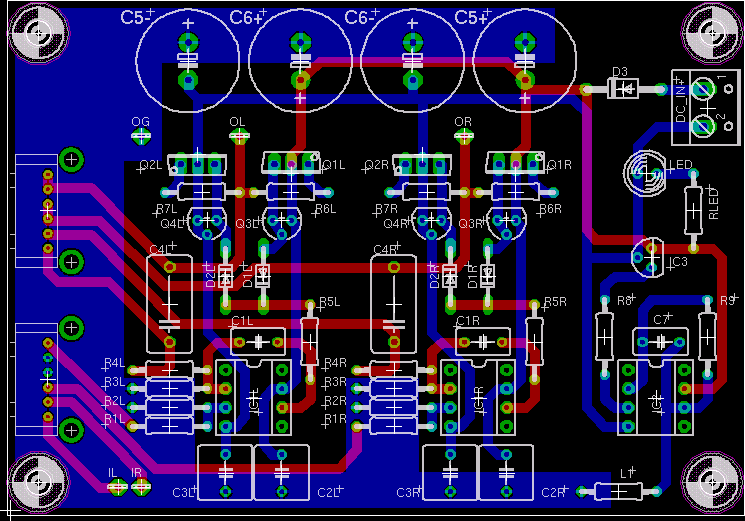
LISA-II-4.gif


Any comments on the layout are most welcome
smily_headphones1.gif


/U.

PS: Is it possible to use the OPA551 as the railsplitter opamp instead of
the LM6171?
 
Aug 8, 2005 at 9:07 PM Post #2 of 40
I tried it on a piece of stripboard, it's nice sounding although I'm not going to draw any comparisons with other topologies... The OPA551 should be fine to go in that position, you're really looking for the current drive. Probably better than the 6171 due to the lower bandwidth.

Looks good
smily_headphones1.gif
 
Aug 8, 2005 at 10:09 PM Post #3 of 40
Do you have a schematic handy?

[edit]: Oh, i shoulda looked harder on the site.

Correct me if im wrong, but isnt it essentially a PIMETA with a bass boost circuit?

[edit2]: Or not. I just had a proper look at the schematic. I noticed it has no DC blocking caps, does it have other circuity to prevent DC?

Rob.
 
Aug 9, 2005 at 7:47 AM Post #7 of 40
Quote:

Originally Posted by amb
Btw, Nisbeth, nice work. The general layout sort of resembles a mini-M³.
cool.gif


Hehe, I know but as you can see from the IPS thread it's not my fault - it's jamont's
biggrin.gif


The eagle files are available for download here If anyone is planning to have boards made, please check my schematic carefully before sending off the files (and let me know if you find any problems
smily_headphones1.gif
)


/U.

EDIT: If anyone plans to have boards made I'm interested in a board or two. Send me a PM
smily_headphones1.gif
 
Aug 9, 2005 at 8:23 AM Post #8 of 40
If anyone is making boards up send me a PM to please
smily_headphones1.gif


Im having a hard time understanding the schematic and what everything does, but it looks interesting.

Rob.
 
Aug 9, 2005 at 8:27 AM Post #9 of 40
Quote:

Originally Posted by robzy
If anyone is making boards up send me a PM to please
smily_headphones1.gif


Im having a hard time understanding the schematic and what everything does, but it looks interesting.

Rob.


I'm tempted to.. but as I said to niz in pm, if I do, then I'll probably shoot for configuring for a dual opamp rather than two singles..


we'll see.. I have a lot on my plate at the moment
 
Aug 9, 2005 at 9:09 AM Post #10 of 40
Nisbeth: is it just me or are the electrolytic caps positioned wrong?

two of them seem to be connected to ground/ground as opposed to ground/positive

edit: nah my mistake.. sorry
rolleyes.gif
 
Aug 9, 2005 at 10:16 AM Post #12 of 40
Quote:

Originally Posted by robzy
Correct me if im wrong, but isnt it essentially a PIMETA with a bass boost circuit?


I'd rather say it's a cut down M³ with a BJT push pull buffer instead of the mosfet buffer

Quote:

Originally Posted by robzy
I just had a proper look at the schematic. I noticed it has no DC blocking caps, does it have other circuity to prevent DC?


nope, the amp is dc-coupled and doesn't incorporate a dc-servo or something like that. With a 50k volume pot you can simply wire input caps between the RCA jacks and the input pads. 0.22uF or 0.33uF polyprolylene caps would be fine.
 
Aug 9, 2005 at 10:34 AM Post #13 of 40
Quote:

Originally Posted by steinchen
I'd rather say it's a cut down M³ with a BJT push pull buffer instead of the mosfet buffer


So like a ppa..

wonder if you could use mosfets..
 
Aug 9, 2005 at 11:18 AM Post #14 of 40
Quote:

Originally Posted by Jazper
wonder if you could use mosfets..


generally speaking: yes. But mosfets need a much higher bias (at least 50 or 60mA) and need to be heatsinked. Furthermore (with LISA) the bias-diodes D1 and D2 must be replaced by pots for bias adjustment and resistors are advisable at the gates of the mosfets. To sum it up it's better to build an M³ if you want the mosfet buffer.
 
Aug 9, 2005 at 11:24 AM Post #15 of 40
Quote:

Originally Posted by amb
Btw, Nisbeth, nice work. The general layout sort of resembles a mini-M³.
cool.gif


Or a mini PPA.....
wink.gif
 

Users who are viewing this thread

Back
Top