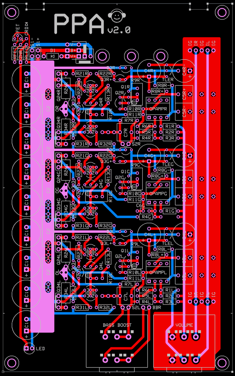
PPA v2 Project Announcement
Jan 20, 2005 at 3:14 PM Post #17 of 106
is class A/B a concession to portability (low current) ? I'd rather prefer pure class A since headphones need only little power and heat dissipation isn't problematic (if you don't use opa633
wink.gif
). Is it possible to adjust the buffers further towards class A ?
 
Jan 20, 2005 at 4:22 PM Post #20 of 106
We're probably going to recommend a default bias of about 20mA, so it probably is in fact class A already.
 
Jan 20, 2005 at 7:34 PM Post #21 of 106
Why not put the ground channel farthest away from the vol pot, so the cable length to R channel will be shorter.

The discreat buffer take up much more space.
Luckily there's enough free space around the buffer sockets on my PPA clone, so maybe I will see myself building a PPA V2 overdrive (I don't think there's enough space on official PPA v1.X PCB) , or just call it P2 overdrive in short.
 
Jan 20, 2005 at 7:54 PM Post #22 of 106
Yeah, whether the amp is class A or class AB depends on what kind of load and what sort of voltage swing you want out of it. The heavier you bias the output stage (more current), the amp will remain in class A for lower impedance phones over a greater output voltage range. With 300 ohm phones, the max peak output current just before clipping (assuming 24V power supply) is about 50mA, and as long as the quiescent current is more than half of that, then the amp will be class A. For a PPA v2 set to quiesce at 20mA, it will remain in class A over the full output swing for hi-Z loads only, so for lower impedance cans it will be class AB.

In PPA v1, you can't adjust the quiescent current of the output buffer (they're fixed at about 8.5mA per HA5002), but you could change the number of stacked buffers. When you use all four buffers, the quiescent current is quadrupled. In PPA v2, the quiescent current is adjusted via a trimpot, but there is a limit on how high you can adjust it due to lack of heatsinking and ventilation, and for battery-compatibility concerns. RMAA tests have shown that the PPA's distortion increases with lower impedance loads, but increasing the number of output buffers on PPA v1 (or adjusting for higher quiescent current on PPA v2) reduces that tendency greatly.

In the M³, due to the bigger MOSFETs and ample heatsinking, the output stage is biased much more heavily so the amp will stay in class A for virtually any kind of headphone load. This is demonstrated by RMAA as well, showing no difference in distortion whether the load is 300 ohms or 32 ohms.
 
Jan 20, 2005 at 8:31 PM Post #23 of 106
doobooloo: Show me the caps! (The ones that will fit C2 with 600mil lead spacing.) I'll add some 400mil C5 pads, that way you can use the same caps for C2 and C5.

skyskraper: Clearly you have earned your custom title: "Is there any ETA on boards?"

steinchen: I cut and pasted my opamp recommendations from the original PPA site. I thought a bit about doing that, but decided not to worry about it since the OPA367 can be removed from the list if it turns out to be problematic.

zhoufang: The ground channel is the only one that will fit in the middle because it is narrower than the other two channels. Chalk it up to the congested layout. It's a price we pay for Eurocard compatibility.

amb: Nice posts, you did a great job of answering Magsy.

PPA v2:
AC or battery operation
Eurocard format (160×100mm) (6.3×3.937") fits in a Eurocard case
4A MJE243/MJE253 or 1.5A BD139/BD140 TO-225 BJT output devices
10-20mA bias, no heat sinks

M³:
AC only
7×5" (178×127mm) requires a custom or oversized case
18A IRFZ24N/IRF9Z34N TO-220 MOSFET output devices
80mA bias, heat sinks
 
Jan 20, 2005 at 8:51 PM Post #24 of 106
Some I found that could work are:

WIMA MKS-4
3.3uF/63VDC PCM15, 6mm x 18mm

WIMA MKS-4
2.2uF/63VDC PCM15, 6mm x 18mm

But then I guess there's an equivalent one at 5mm x 10mm, so the extra lead spacing won't add any real value unless the smaller cap is harder to find.

WIMA MKP-4
0.22uF/100VDC PCM15, 5mm x 18mm

WIMA MKM-4
0.22uF/250VDC PCM15, 5mm x 18mm

Vishay MKT1822 (available from Mouser)
1.0uF/63VDC PCM15, 5mm x 18mm

These are some options that have 200mil width and 600mil lead spacing. Anyway, will 6mm width caps fit?
 
Jan 20, 2005 at 9:33 PM Post #25 of 106
6mm = 236mils. This may be enough clearance if the C1 electrolytics are not fatter than 500mils. 18mm = 709mils. They may not seat since they will be touching end to end at 700mils, on the other hand, they may actually be shorter. Longer and shorter caps could be alternated to circumvent the length issue. Bottom line: We won't know until someone tries them in real life, because these parts often vary substantially from their specified dimensions. I'll add the pads.

Since our development list has been quiet I thought it would be a good idea to mention the following issue: Tangent asked for the center LED pads overlapping the bass boost pot. PPL expressed concern that leakage currents and capacitive coupling might be a problem. I don't care if we keep the extra LED pads or not, but observe that the LED is not a dynamic load. If it is really a problem then of course we should get rid of it, on the other hand, why sack a requested feature needlessly if it is harmless. Thoughts?
 
Jan 20, 2005 at 9:57 PM Post #26 of 106
Quote:

Originally Posted by morsel
6mm = 236mils. This may be enough clearance if the C1 electrolytics are not fatter than 500mils. 18mm = 709mils. They may not seat since they will be touching end to end at 700mils, on the other hand, they may actually be shorter. Longer and shorter caps could be alternated to circumvent the length issue. Bottom line: We won't know until someone tries them in real life, because these parts often vary substantially from their specified dimensions. I'll add the pads.

Since our development list has been quiet I thought it would be a good idea to mention the following issue: Tangent asked for the center LED pads overlapping the bass boost pot. PPL expressed concern that leakage currents and capacitive coupling might be a problem. I don't care if we keep the extra LED pads or not, but observe that the LED is not a dynamic load. If it is really a problem then of course we should get rid of it, on the other hand, why sack a requested feature needlessly if it is harmless. Thoughts?


Would it be possible then to add jumpers that connect the left LED pads and the center LED pads so that the center LED pads aren't connected to anything unless specifically wired to be so?

Honestly though how much of a damage can it do, I would like to see it left there for the sake of convenience, if one really desires that nothing be under the bass boost pot they can always cut the trace or something, no?
 
Jan 20, 2005 at 10:47 PM Post #27 of 106
LED trace disabling jumpers, gah!
eek.gif
Over my dead body.
rolleyes.gif


If it comes to that, let them wire their LEDs like normal people. (What normal people? Well, we can pretend, at any rate.) My only concern is if there is a real world problem with these traces. For what it's worth, M³ does not do this, a center mounted LED must be wired from the pads on the side.
 
Jan 20, 2005 at 11:22 PM Post #28 of 106
ppa v1914 changes

added new pads for C2 and C5
increased the window width to 100mils just like on M³
(it's easier to solder this way)
reverted C4 from larger custom pads to standard 56/29mil pads
(long ago I gave C4 larger pads to match the window clearance of the film caps)

I'm not keeping the old layout gifs online, merely replacing the current gif.

ppa.gif
 
Jan 20, 2005 at 11:40 PM Post #29 of 106
Quote:

6mm = 236mils. This may be enough clearance if the C1 electrolytics are not fatter than 500mils. 18mm = 709mils. They may not seat since they will be touching end to end at 700mils, on the other hand, they may actually be shorter. Longer and shorter caps could be alternated to circumvent the length issue. Bottom line: We won't know until someone tries them in real life, because these parts often vary substantially from their specified dimensions. I'll add the pads.


Would it be possible just to move the C1 banks slightly to the left? That shouldn't create any slide-mount problems right?

Anyway, it's nothing crucial anyway.
wink.gif
Just a thought.
 
Jan 20, 2005 at 11:57 PM Post #30 of 106
The C1 row is as close to the edge as can be. Certain varieties of electrolytics touch the Hammond 1455 case inside wall. The extra space you see goes into the case slots that hold the board in place.
 

Users who are viewing this thread

Back
Top