Post pics of your solder joints: reference thread for DIYs
Apr 6, 2005 at 8:23 PM Post #46 of 77
I'd tend to agree that delicate components (opamps, etc) should have low wattage iron whenever possible, but that connectors usually solder best for me (with minimal chance of melting anything) by using hotter iron. Of course, your choice of solder will matter too.
 
Apr 6, 2005 at 8:28 PM Post #47 of 77
Quote:

Originally Posted by audiomortis
I didn't say that you can't dammage them, but it's not going to happen in a second. I've done hundreds of XLR and Phono connectors and I don't think I've ever totally fried one. when you're working on a board, you can fry an opamp in no time flat. Normal connectors are much more forgiving than sensetive electronic devices. If you're doing anything remotely right, you're not running much risk with connectors. You've got a little bit of time at a moderate temp on most connectors before they warp or melt, but again, there's no substitute for experience.


XLRs and 1/4" connectors are pretty impervious to heat, Youd need to hold the iron there for a while to damage.

mini connectors and RCA connectors are totally opposite, I believe this is where you make in incorrect assumption.

mini and RCA connectors will melt significant faster then any XLR and Phono connector. Ive soldered every connector you mentioned and then some. an XLR is less prone to melting as fas as the opposing connectors Ive listed.

this is why RCA connectors offer teflon dielectric around the signal pin on higher end models, to prevent the misalignment of the pin during soldering.
 
Apr 6, 2005 at 9:32 PM Post #48 of 77
even if a RCA is a little more fragile than an XLR, it's still not a huge concern or something you have to be super careful with. Yeah, if you sit there and cook it with your iron, it will be ruined, but you don't have to rush yourself through it too much. In the context of somebody asking what temp to use, I say don't worry about it too much, you're not going to destroy it as easy as an opamp or something.
 
Apr 8, 2005 at 5:46 AM Post #49 of 77
Is it bad to use a connector twice? Like de-solder it and reuse it?
 
Apr 8, 2005 at 5:49 AM Post #51 of 77
TY. Im working on my first cable right now and I think I want to re-make it.
 
Apr 8, 2005 at 5:52 AM Post #52 of 77
I use a copper desoldering braid. You can pick it up at rat shack.

it pretty much takes all the solder off from prior use and makes the platform perfectly clean again
smily_headphones1.gif
 
Apr 8, 2005 at 3:55 PM Post #54 of 77
Quote:

Originally Posted by waltermeyer
Im new to soldering, so I was wondering what the temp. range should be when soldering with the WBT silver solder? I got 1/2 lb. of it and abunch of star-quad and Neutrik connectors, and want to start making some of my own cables. But the soldering station I bought has a temp. dial. So I dont know if I should just plug in and go, or what. Any info? Thanks!


When I was working in the industry, the standard temperature we used for our soldering stations was 600°F using 63/37 SnPb eutectic solder. When we started using tin-silver-copper solders we had to bump up the temperature to around 650°F. You can bump the temperatures up about 20-50 degrees for soldering larger parts such as 1/4" jacks & power cords.
 
Apr 9, 2005 at 7:47 AM Post #55 of 77
Well here it is. Its my first cable. Well second if you count one practice mini to mini, but I went into that one knowing it was only practice. Anyone feel free to critique it. I would love to hear some constructive criticism. I want to get better. Although I am very happy with the way this one turned out. It sounds incredible too. I hope the pics are good enough to see the solder joints.

http://img.photobucket.com/albums/v2...ble4-05001.jpg
http://img.photobucket.com/albums/v2...ble4-05006.jpg
http://img.photobucket.com/albums/v2...ble4-05007.jpg
http://img.photobucket.com/albums/v2...ble4-05008.jpg
http://img.photobucket.com/albums/v2...ble4-05010.jpg
http://img.photobucket.com/albums/v2...ble4-05012.jpg
http://img.photobucket.com/albums/v2...ble4-05013.jpg
http://img.photobucket.com/albums/v2...ble4-05014.jpg
And one more, of my messy work area.
http://img.photobucket.com/albums/v2...ble4-05016.jpg
Enjoy.

P.S. - Sorry, I only know how to post links, I dont know how you all post these big pics. It always says it wants to restrict the size of mine to something very small.
 
Apr 9, 2005 at 8:19 AM Post #56 of 77
hey walter,

photobucket has a file size limit restriction, you just need to save the pics at a lower quality or shrink them a bit, for photobucket to accept them.

if you want to post the pics directly you need to use the IMG tags

regarding the cable, nice job for a first time. your solder joints are clean and wet looking.
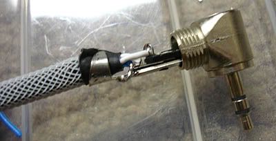
some contructive critism? You seemed to have stripped too much insulation and jacket on your first cable. i.e. on the switchcraft, the clamps should be the jacket like so

dualwall.jpg


you can avoid over stripping by placing the conencto next to the wire for placement prior to stripping. OR you can over strip the leads so that you can fit the clamp over the jacket, then cut off the excess wire on the leads.

be sure to snip off the excess wire exposed past the sildering point with some fiskers.

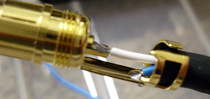
for the RCA connector, you should strip just where the insulation meets the signal pin.

solderjoint.jpg


other then that, I am impressed!

I look forward to you R/A mini cable!
 
Apr 9, 2005 at 8:33 AM Post #57 of 77
I got you. Thanks. My next one will be a regular set of RCA's. I will keep that in mind when I make them.
 
Apr 9, 2005 at 4:12 PM Post #58 of 77
Quote:

Originally Posted by waltermeyer
Well here it is. Its my first cable. Well second if you count one practice mini to mini, but I went into that one knowing it was only practice. Anyone feel free to critique it. I would love to hear some constructive criticism. I want to get better. Although I am very happy with the way this one turned out. It sounds incredible too. I hope the pics are good enough to see the solder joints.


Nice work! I'm about to start my first cable, too. How long did it take you?
 
Apr 9, 2005 at 8:19 PM Post #59 of 77
When I'm soldering a PCB I like to ensure that a dry mechanical joint is in place before I flood solder into the joint, the pin witness method is fine but the only connection between pad and leg is by solder... easy to disassemble if the component should ever have to be replaced but I prefer the bend and snip and solder method as it not only provides a dry mechanical joint but the finished soldered joint is a nice shiny dome shape which not only looks good but makes cleaning the board very easy as there are no sharp protusions.

I basically insert the component, bend the legs over so they make firm contact with the pad and then snip the leg flush with the edge of the pad at an angle ( \ ) that's the dry mechanical connection...... I then apply heat to the component leg and flood solder into the joint which really makes a strong reliable and nice looking domed joint.

attachment.php


Some people swear by this method, others swear at it but I can honestly say I have never experienced a dry joint or a dodgy joint using this method, you've got the best of both worlds... a dry mechanical joint supplemented with solder as opposed to the pin witness technique where solder is the only thing making the connection.

Production lines (used to?) use the pin witness technique as it's faster to populate the boards that way and easier to remove the component should the item ever require servicing... the boards are populated with components on a jig which is flipped over and then soldered and snipped...... it's not necessarily the "correct" or "best" way to do it but it sure is the quickest way to do it if humans are doing the soldering...... it used to be called "pin witness" to Canadian standards, god only knows what it's called now
confused.gif


My camera is only a 1 megapixel effort but here's an example of the bend, snip and solder technique:

e.jpg


5.jpg
 
Apr 9, 2005 at 11:24 PM Post #60 of 77
Quote:

Originally Posted by The Monkey
Nice work! I'm about to start my first cable, too. How long did it take you?


This one only took me like one hr. It wasnt that bad. But I also have alot of nice tools that make working much faster and pleasant. I can see me getting faster and more comfortable with it and being able to make one in like 20-30 min.
 

Users who are viewing this thread

Back
Top