Phono Preamp RIAA help.
Oct 15, 2005 at 5:13 AM Thread Starter Post #1 of 19

Garbz

Headphoneus Supremus
Joined
May 19, 2004
Posts
3,573
Likes
14
I'm currently working on the El Cheapo preamp from DIY audio which has the following single opamp design:
http://www.diyaudio.com/forums/attac...amp=1077382697 for MM cartridges. And I ran into issues with the RIAA curve and with output caps.

First problem is the RIAA curve.

According to this site: http://www.euronet.nl/~mgw/backgroun...kground_1.html The ideal RIAA curve has the following values for a given frequency. My TINA SPICE simulation is to the right:

Code:

Code:
[left]Freq,---RIAA,---SPICE 20 +19.2 18.83 50 +17 16.29 100 +13 12.31 500 +2.7 +2.45 1k REF REF 2k -2.5 -2.83 5k -8 -8.13 10k -13 -11.73 20k -19 -14.56[/left]

The problem with this is at the high end things are about 4dB above the desired value. My speakers are bright enough as it is without this boost in treble. Any clever ideas with the values in the feedback loop to fix this?

The other problem occures when I'll bias the opamp into class-A. Doing so causes DC on the output so I'll need to add DC blocking caps. I'd like to use things I have on hand and need help with values since I forgot how to calculate a low pass formula.

My amp's input impedance is 330kohm. I have on hand nice 1uf caps, nice 0.33uf caps, and worst comes to worst, 470uf BG electrolytics if it comes to it. So can I grab some insight or the RC high pass formula thanks.
 
Oct 15, 2005 at 7:33 AM Post #2 of 19
Quote:

Originally Posted by Garbz
The problem with this is at the high end things are about 4dB above the desired value. My speakers are bright enough as it is without this boost in treble. Any clever ideas with the values in the feedback loop to fix this?


Use your simulator and increase the 330pF capacitor in the feedback loop to a slightly higher value and you will find the proper value that would give a flat(ter) response.

Quote:

The other problem occures when I'll bias the opamp into class-A. Doing so causes DC on the output so I'll need to add DC blocking caps.


I assume you will be using some sort of CCS at the output tied to the negative rail. While doing so will cause the opamp to source current, the actual DC offset at the output should not be impacted. For a phono stage, an output coupling cap is probably a good idea anyway because the gain is so high (especially at DC).

Quote:

My amp's input impedance is 330kohm. I have on hand nice 1uf caps, nice 0.33uf caps, and worst comes to worst, 470uf BG electrolytics if it comes to it. So can I grab some insight or the RC high pass formula thanks.

f = 1 / (2 * pi * R * C)

So, for 330K ohm load impedance, and a 1uF output coupling cap, the corner frequency will be about 0.5Hz.
 
Oct 15, 2005 at 2:04 PM Post #3 of 19
yeah thanks amb. I simulated the output cap. A bode analysis showed not only does the fequency make little difference, but there's also no phaseing. At 50k input impedance it's a different story though. Minor phasing, but no drop in freq.

I got the RIAA values within -0.02dB > 1khz, +0.1dB at 100hz, and +1db at 20hz. That should give me a slight boost in the low end, and in the process i eliminated 2 parts. The nominal gain at 1khz is 42dB

Parts are now:

475ohm -> 470ohm
681k -> 680k
56.2k -> 56k
2.21k -> omitted
330p -> omitted

The bias circuit is basically 2 fets + resistor. Depending on what I can source. It may for a while end up being a plain resistor only, depends what I find. Wouldn't connecting the output to the negative rail with a resistor effect the DC? or does the opamp compensate with it's feedback loop? What if the 200r output resistor was omitted?
 
Oct 15, 2005 at 2:19 PM Post #4 of 19
are you locked into a particular design (the above) or is this still open to ideas ?

First off the OPA637 is a better choice than the OPA627 and is geared specifically to the high gain low noise stage like phono and mic preamps.I have also used the LT1028 and AD797 successfully so there are some good choices out there is you are doing a "scratch" build

First off this is a really tidy starting point.An AES reprint by Walt Jung

http://home.comcast.net/~walt-jung/w...no_Preamps.pdf

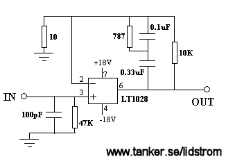
The ULTRA simple would be this straight from the LT1028 data sheet :

1028riaa.gif


low parts count,low noise and the really cool part ?

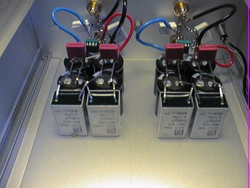
So simple even a "dead bug" type layout works :

riaain.jpg


That is THE coolest RIAA preamp layout I have ever come across and so simple to do a no brainer for a first phono stage.

the rest is here

http://www.tanker.se/lidstrom/eng/slriaa.htm

Another LT design is this puppy that uses a low noise opamp in class-A plus a buffer to drive the eq network.Also straight from the LT pages

1293.jpg


http://www.linear.com/pc/downloadDoc...28,P1219,D1683

finally an "ultimate" opamp based phono stage which is not cheap but sounds great.This one I have actually built and used until i moved up to a discrete jfet stage then a triode stage (natural progression ?
tongue.gif
)

http://www.users.nac.net/markowitzgd/phonopre.html


Usually if you check the low noise opamp data sheets from each manufacturer there will be a design for a phono preamp so check the AD797 sheets and others for more ideas

If you are set on the OPA chip I really would go with the 637 which is far better than the 627 for really high gain use
 
Oct 15, 2005 at 4:10 PM Post #5 of 19
If you want to get the equalization correct, it's much better to calculate the proper component values than to try to juggle values in a simulator or actual circuit. There's just too much interaction between the components to be able to get the most correct result this way.

Fortunately there was a paper published back in 1979 that made it possible to calculate the correct values for real-word circuits. This is the famous "On RIAA equalization networks" by Stanley P Lip****z. Journal of the Audio Engineering Society. 1979. June. Volume 27. Number 7. pp458-481. This handles a number of different cases: inverting and non-inverting amplifiers, limited open loop gain and bandwidth, etc.

You might find it in your local library, or it can be purchased from the AES:

<http://www.aes.org/e-lib/browse.cfm?elib=2930>

This paper was used as the basis for a later technical article in Audio Amateur magazine by a certain head-fier which showed how to calculate the proper RIAA component values for a tube phone stage like that used in the Audio Research SP-6/6 etc. and Dynaco PAS preamps.
 
Oct 15, 2005 at 5:17 PM Post #6 of 19
I tried to actually steer from doing the RIAA EQ and towards a more ready to build type design that would give you room for tweaking by ear once built since you are starting out with a "known" response that has grahic representation.

but the theory is also cool and a nice exercise if not for actual useage and if you REALLY want to be baffled then....................

Page http://www.smartdev.com/RIAA.html

Print Version http://www.smartdev.com/chpt14.pdf


There are a boatload of RIAA calculators online but these guys have the easiest to use one and maybe since phono is the main thrust of their business a good one by comparison :

http://www.kabusa.com/frameset.htm?/phonpre.htm


Of course these do not always address the real time constant but only the theoretical on paper one that really is not what the real world situation is (the above "el cheapo" adresses this)

http://www.klaus-boening.de/html/timeconstant.html

http://www.euronet.nl/~mgw/backgroun...kground_1.html


I kinda lile the idea of the "trimmed" EQ that Manley Uses.No circuit but a nice explanarion as in all their product Manuals : http://www.manleylabs.com/PDF/HIFI_M...082004ver2.pdf
 
Oct 15, 2005 at 5:44 PM Post #8 of 19
Quote:

Originally Posted by rickcr42
I tried to actually steer from doing the RIAA EQ and towards a more ready to build type design that would give you room for tweaking by ear once built since you are starting out with a "known" response that has grahic representation.


OK. Since I had a bunch of experience in this, I just wanted to point out that it was possible (and really not so difficult) to compute the correct values that would give the proper, flat response, and also that it was very hard to archive this by trial and error (with the result that the response is not flat but lumpy, and the trial and error method usually results in just moving the lumps around and not really flattening them out.)

Far too many high end preamps were manufactured with inaccurate RIAA equalization, not because it sounded better that way, but because the designer or manufacturer didn't know how or didn't care to get the values right. The paper by Lip****z in 1979 meant there was no longer any good excuse for this, or for using values that assumed infinite negative feedback etc. He did all the hard work accounting for these effects and showed how to get correct active equalization even when the amplifier's gain and bandwidth aren't very high.

'Nuff said from me on this.
 
Oct 15, 2005 at 6:03 PM Post #9 of 19
Quote:

OK. Since I had a bunch of experience in this, I just wanted to point out that it was possible (and really not so difficult) to compute the correct values that would give the proper, flat response, and also that it was very hard to archive this by trial and error (with the result that the response is not flat but lumpy, and the trial and error method usually results in just moving the lumps around and not really flattening them out.)


all good !
icon10.gif


I was just expanding on the answer a bit and offering some more content.I am one that thinks you never have too much information only not enough and like to not only read all sides but present it for others so they too can decide what they think is the correct way through experimenting.
Sometimes this is information overload for the newbie so I also am of the opinion to go with the simple and tested at the crawl stage,then tweak that for the "baby steps" stage of developement and once a person learns what eactly it is they are looking to accomplish by having some real world experience in their own system can go back to the body of content and take what they need to get where they are going to suit their own taste and particular needs.


Anything you add is only a plus and worthy so add away man
cool.gif
 
Oct 15, 2005 at 7:15 PM Post #10 of 19
Quote:

Originally Posted by Garbz
I got the RIAA values within -0.02dB > 1khz, +0.1dB at 100hz, and +1db at 20hz. That should give me a slight boost in the low end, and in the process i eliminated 2 parts. The nominal gain at 1khz is 42dB

Parts are now:

475ohm -> 470ohm
681k -> 680k
56.2k -> 56k
2.21k -> omitted
330p -> omitted


Yeah, the 2.21KΩ resistor was actually introducing another pole and causing the response to flatten out at the high end (causing the rise that you observed). Typical RIAA feedback networks don't have that resistor. The reason the original designer put it there was probably to keep the HF gain more than 5 to appease the OPA637. I wonder if it would become unstable without it...

Quote:

The bias circuit is basically 2 fets + resistor. Depending on what I can source. It may for a while end up being a plain resistor only, depends what I find. Wouldn't connecting the output to the negative rail with a resistor effect the DC? or does the opamp compensate with it's feedback loop? What if the 200r output resistor was omitted?


The negative feedback loop keeps the DC offset from being pulled low. The 200Ω resistor serves to isolate cable capacitance from upsetting the opamp, and prevents potential damage if the output was shorted to ground.
 
Oct 16, 2005 at 1:21 AM Post #11 of 19
OPA627
confused.gif
I don't think I menitoned that chip. It's been the OPA637 from the start.

I haven't locked myself into a specific design, but KISS. Ideally for me is a single OPAMP no buffer, low parts count, and if the RIAA curve can't be matched exactly lead towards lower trebble and higher bass since my speakers swing the otherway because of room dimensions.

I just chose that design from a head-fi search and will bias it with a cascode jfet into class A. I'll stick with my design over the simple one you posted Rick because it's well ... the same with some different values.

Also the Analogue Addicts design you posted is what the original is based off. It was simply modified by removing all the MC circuitry, also I pulled the 330p off and change the values slightly and it fits the RIAA curve better, not only that I changed the parts based on what I most easily can source. All parts are standard resistor and capacitor values now.

Rick you need professional help. A vinyl junkie over the edge
600smile.gif
That said I read everything, maybe not now, but I have so far worked my way through everything related you have posted in a thread
cool.gif


Trbl I have a spreadsheet to calculate the exact values, the problem is when I run it through a formula I get values for the RIAA circuit which when matched to the nearest parts I can source are waaaay off. The closest I got was about 2db over the range without resorting to trial an error.

AMB that's an interesting thought, I wonder if I can model this in TINA to remove the guesswork ... but mind you why would it need the HF to keep it stable? Typically when i've seen people try and stabalise an opamp they put a low pass filter in.
 
Oct 16, 2005 at 1:49 AM Post #12 of 19
Quote:

Also the Analogue Addicts design you posted is what the original is based off. It was simply modified by removing all the MC circuitry, also I pulled the 330p off and change the values slightly and it fits the RIAA curve better, not only that I changed the parts based on what I most easily can source. All parts are standard resistor and capacitor values now.


Every single part in that design is optimised to the design and if you change one thing you are making an entirely new design and one having very little sound wise to do with the original.
One thing about any design TL does is choose every single part for a specific sound in balance with every other specific part.Something I found out the hard way by building some really bad sounding "clones" that turned out to be quite nice once I followed the exact BOM.Took a while for me to realise the sum of the parts really is greater than the individual parts when the correct combinations are found.

I also think you make a huge mistake trying to use the RIAA EQ as a system EQ to make up for deficiencies in other areas.This is a very deleicate thing at extrmemly high gains and the good ones do not sound that way accidently or by plugging in a simple formula.I would build the best of whatever I was building then adress any systemic limitations where they need to be addressed and when I could.

for arguments sake :

You eq the phono stage to sound good in system by changing the parameters to fit what you have,something I mostly agree with but in this case,what about CD ? Any Radio ? Analog tape ? Multimedia or portable source ?Are you willing to equalise each one to sound good in the system ?

what happens when you plug that device into another system (portables) is your "correction" defeatable ?

I usually attack system wide problems at the system level and if there si a perceived brightness that i feel should not be there I first try the "acoustic" fix which is looking around the room to see what could possibly be the cause and then taking steps but if that is not an option then a simple single pole filter should deal with it nicely if tuned to the correct point.You would be surprised what a -3 db @ 30khz can do for a "harsh" sounding system.

You caould also look into a passive bandpass filter that follows the infamous/famous "BBC Dip" used to voice most vintage brit speaker systems and one that produces a very civilised sound if that is what you are seeking (and i have a suspician it is
tongue.gif
)

Quote:

Rick you need professional help. A vinyl junkie over the edge That said I read everything, maybe not now, but I have so far worked my way through everything related you have posted in a thread


worse than you think man.Far worse
rolleyes.gif


someone gave me a couple of boxes fully loaded with Lps and 45's that i am presently wading through and "culling" those too far gone or of zero musical interest (C&W
tongue.gif
).The Motwon 45's alone gave me a serious woodie and the wife thinks i may have finally slipped over the edge of sanity.The goofy locked on smile and my wife telling me "Rick ! Wipe that drool from your chin !" damn embarrassing man
very_evil_smiley.gif


Quote:

OPA627 I don't think I menitoned that chip. It's been the OPA637 from the start.


When you get to be my age and considering all the self abuse I did in my youth (party monster
icon10.gif
) and if that is ALL I imagined then I consider it a GOOD Day ! I am surprised I have a single pair of brain cells left to keep each other company and those two functional on any level above comotose
cool.gif
 
Oct 16, 2005 at 3:06 AM Post #13 of 19
Hahahah
icon10.gif


Currently my CDs sound perfect with no EQ. The entire setup is fast and jumpy since I put the transformers in a lot of dullness has been eliminated. I'm woried that the original design simulated through TINA was 3db higher in treble then the RIAA eq. I'm actually trying to do the opposite and prevent a bright EQ comming from the phono stage.

The RIAA eq makes a record sound flat doesn't it? If so I'd much rather put up with 1db boost below 1khz then a 3db boost at about 5khz, oh providing TINA gives a truely accurate simulation. I'm not sure about that since this is the first time i've ever tried simulating anythin. EIther way a boost in treble would probably push my system a bit over the edge. That said you raise valid points about the original design. I think i'll build it in a way that I can roll parts at leasure, afterall I can put in the option for the extra resistor and cap and simply omit / jumper when necessary.

Anyway i'm not worried about other people or upgrading. I'm a tinkerer by nature. I'm more happy having my system sounding perfect, and if I upgrade a bit of surgery and the smell of solder fumes keeps me heatly anyway.
 
Oct 16, 2005 at 4:44 AM Post #14 of 19
Quote:

Originally Posted by amb
Yeah, the 2.21KΩ resistor was actually introducing another pole and causing the response to flatten out at the high end (causing the rise that you observed). Typical RIAA feedback networks don't have that resistor. The reason the original designer put it there was probably to keep the HF gain more than 5 to appease the OPA637. I wonder if it would become unstable without it...


As far as I can tell, it's extremely popular with opamp based designs to add a 4th pole at about 50 KHz. (The so-called "enhanced" RIAA curve, see this page.)
 
Oct 16, 2005 at 6:27 AM Post #15 of 19
Quote:

Originally Posted by Mr.Radar
As far as I can tell, it's extremely popular with opamp based designs to add a 4th pole at about 50 KHz. (The so-called "enhanced" RIAA curve, see this page.)


Yeah, I read that. However in a non-inverting topology like this one (assuming that the 2.21K resistor is absent), the gain will never go below unity, so there is going to be a built-in shelving effect above 20KHz anyway. The original RIAA EQ curve is supposed to continue to drop above 20KHz, so this circuit already gives an effective "boost" above 20KHz. The 2.21K resistor shifts the gain up a bit so that it doesn't drop to unity. With the values chosen, it will go down to a minimum gain of (2.21K / 475) + 1 = 5.65. This is suspiciously close to the minimum recommended gain of the OPA637.

To avoid the additional shelf at the top end, some designers prefer to use either a passive low-pass filter for the HF portion of the RIAA curve (i.e., Erno Borbely, with his two-stage circuits), or to use an inverting topology in order to more closely implement the RIAA standard. This is in stark contrast to the "enhanced RIAA" scheme described in the abovementioned link. It is arguable that such a modification really isn't an enhancement at all.
 

Users who are viewing this thread

Back
Top