Quote:
Originally Posted by balou /img/forum/go_quote.gif
Replacing the TL071 with a OPA134 might not be a good idea. Of course I don't know the exact circuit of this preamp, but I don't think that they really put the TL071 inside the audio chain.
The TL071 most likely just serves as a DC servo. The OPA134 may have worse DC performance (it's a opamp specially designed for music after all). Nice reading about dc servos: http://www.head-fi.org/forums/showthread.php?t=169016
|
True, it could be. It's odd to see six channels of opamps in a phono preamp - my dinky little NAD just has just one dual channel opamp.
fwiw the CKKIII has an opa2134 doing DC servo duty, as did the original Kumisa III design.
The 134 series is 2nd bannana to the 132 series, which has better DC specs than the 134, so, there is that, but people seem to find the 2134 does good work in a DC servo.
Googling for a schematic might help us make recommendations here.
Quote:
| I really don't like the opa2134. limited soundstage... ericj made some good suggestions. I personally like the ad8066. the ad797 is a very low noise opamp with a high power supply noise rejection ratio, something that make him interesting in a high gain circuit like a phono preamp - but the lm4562 has similar specs, and it's sound is described as more pleasing (lm4562 'neutral', ad797 'cold'). But you shouldn't believe what some freaks on a freak forum say to you about opamps - test them out yourself |
My little NAD preamp came with a Ti branded ne5532, which probably mops the floor with the JRC chips in this one. The opa2107 is my favorite opamp in most circuits but i have to say i liked the ad8066 better in my phono preamp.
In this circuit, though, you'd have to swap out the regulators for 12v parts to run an ad8066 or most Analog Devices parts - the ad8066 maxes out at +/-12v, the ad8620 at iirc +/-13.5v.
I don't know why the voltage tolerances for the AD parts are typically lower - they just are. fwiw the ad8620 sounds thin and strained at 26 volts and better at 24 or 22 volts.
Conversely, the opa2107 loves voltage and sings at 30v (maxes out at 36v), so might sound real good in this circuit.
Quote:
| about the power supply: the 78lXX series of regulators aren't really that good - a standard lm317 provides way better regulation. and power supply quality is quite important in high gain amplifiers. |
Properly bypassed, they really aint bad, but an ambitious rebuilder might replace the 7815 and 7915 with an lm317 and lm337 on a daughterboard and 'air wire' them into the old regulator spots.
But it wouldn't be the first second or third thing I'd do to this board.
I might just make sure there's a .01uf cap right before each regulator and a .1uf cap right after, just for noise filtering.
Or just not worry about it.
fwiw the power supply in my NAD PP-1 is an lm317 configured as a current source rather than a voltage regulator followed by a cmoy-esq rail splitter. It really works fairly well at these tiny power levels.
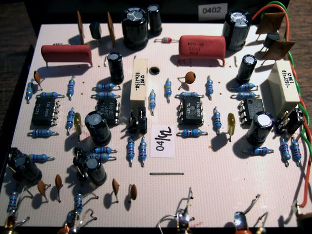
 Are they inductors???)


