ATAT
1000+ Head-Fier
- Joined
- Jan 5, 2005
- Posts
- 1,025
- Likes
- 11
I layed out the schematic and layout for sijosae's MHHA. 2 potential layouts, 2 layer and 1 layer. I'd rather keep it 1 layer (so its possible to etch) but 2 layer seems much cleaner.. I'd HIGHLY appreciate any advice on the schematic as well as the board (I'm unsure of pin-layout as well as the common LED layout..) this is the revision 3 board shown http://www.headphoneamp.co.kr/bbs/zb...sijosae&no=246 here.
I would also appreciate design change suggestions .. such as a CRD instead of the Q1 or whatnot...
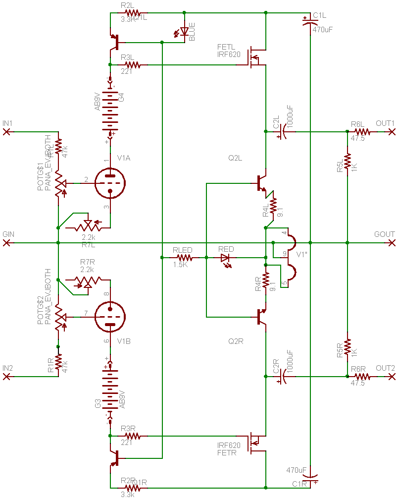
Schematic
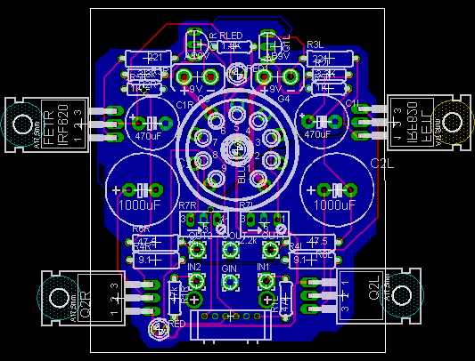
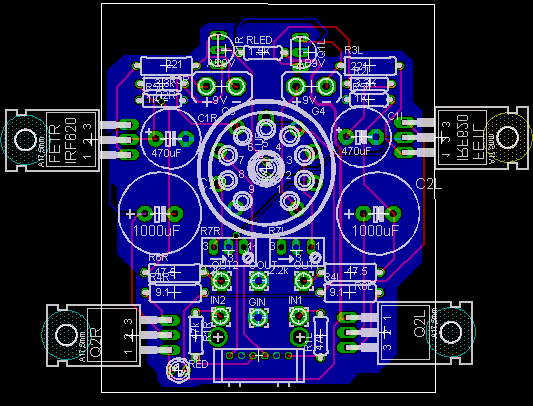
1 Layer
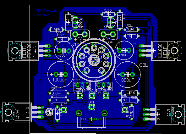
2 Layer
Pending todo:
1. Move 470 uF PSU caps upward.
I would also appreciate design change suggestions .. such as a CRD instead of the Q1 or whatnot...
Schematic
1 Layer
2 Layer
Pending todo:
1. Move 470 uF PSU caps upward.