Parts Bin Amp - PIMETA / CMoy / Other Topology? Mid-Hi current Questions
Apr 8, 2013 at 2:01 PM Thread Starter Post #1 of 13

realpsyence

New Head-Fier
Joined
Apr 7, 2013
Posts
7
Likes
0
Hi Folks, 
 
    Been searching/reading as much as possible but I'm quite new to audio amplifier circuits, though I do build electronics semi-regularly.
 
    Have a CMoyBB (2227) and O2 on the way, but kinda like the idea of a parts-bin special. I've got the following chips in my parts bin:
OPA2132P x1
OPA551PA x2
TLE2426CP (8-pin version) x5
HA3-5002 x5
 
Driving Grados and IEMs so the thinking was to shoot for a current capacity of ~45mA to be safe. 
 
So...before I found the 5002s my thinking was to use the 2132 with local feedback, then buffer each channel with the 551s and provide virtual ground with dual TLE2426s. 
 
Now however, I'm debating whether/where to use the 551s at all, I could conceivably buffer each channel and a single TLE with the 5002s, use global feedback, and ??? Or use the 551 as the virtual ground, or use it to buffer the TLE...
 
Looking for reasonable linearity and will be perf-boarding it, to compare with the two PCB amps I have on the way. 
 
Preferred topology? Good references? I probably have an LM317 or something around here, won't be worried about battery life, but I am lacking a complement of discretes, not sure I totally understand the PreBuf section of the PIMETA (EDIT: Aahh, Class-A biasing, will need to look for 2nXXXXs and decide if the 2132p will be OK in Class-A). 
 
Sanity Check? Thanks everyone, great forum!
 
Apr 8, 2013 at 2:35 PM Post #2 of 13
Driving Grados and IEMs so the thinking was to shoot for a current capacity of ~45mA to be safe. 

 
Where did you get that number? 45 mA into 32 ohms is 65 mW. Since Grados have a sensitivity of about 100 dB per milliwatt, 65 mW sounds like a pretty good way to destroy first your ears, then the headphones.
 
If somehow you were able to prevent the headphones from going nonlinear by that point (i.e. crackle, pop, sizzle) you would expect to get about 135 dB SPL out of them with that kind of power. Roughly what a jet engine puts out, close up.
 
 
my thinking was to use the 2132 with local feedback, then buffer each channel with the 551s and provide virtual ground with dual TLE2426s. 

 
I don't see anything wrong with that.
 
 
I could conceivably buffer each channel and a single TLE with the 5002s, use global feedback

 
That would work, too.
 
It would be a bit of a waste to use OPA551s in a configuration like this anywhere other than to buffer the TLE2426. You could use 2xHA5002 on each of the left and right channels, PPA v1 style. I wouldn't try to shoehorn the third HA5002 in somewhere, just to use it.
 
Unless, that is, you find a good, single-channel op-amp, in which case you could create a PIMETA v2 style virtual ground with the remaining HA5002.
 
 
decide if the 2132p will be OK in Class-A). 

 
If buffered, yes.
 
Apr 8, 2013 at 2:55 PM Post #3 of 13
If you are going to run it off AC full time I would invest the effort to build a dual
rail power supply for it and forget about rail splitting or virtual grounds.
 
Use the OPA2132 to drive one (or maybe even two) of the the HA-5002 buffers
per channel.
Wrap it in global feedback with a gain of two or three.
The OPA2132 will benefit from a couple mA of class "A" bias.
 
I would keep the voltage down, maybe +-9 volts to keep the dissipation
on the buffers to a reasonable level.
 
Happy junk box build!
 
Apr 8, 2013 at 4:06 PM Post #4 of 13
I get 39mA when I calculate for 115dB peaks (32ohm, 98dB/mW) - so yes, 45 is a bit high, but not 135dB high and I always think a little safety factor is useful? Still, we're looking at somewhere around 40, so buffering is in order...
 
 
Consensus (and specification) seems to indicate the 5002s the better buffer for the L/R channels, so we'll go with that. I'm happy with G=2 and global feedback. Cool.
 
3rd channel is the curiosity at the moment.
If you are going to run it off AC full time I would invest the effort to build a dual
rail power supply for it and forget about rail splitting or virtual grounds.

Interesting Avro_Arrow - hadn't thought of that. This will be largely a desktop amp but I'd have to find a transformer, no? Can't be tying up the bench supplies for this.  I do like the idea of not worrying about the virtual ground...just seems like a possible headache, especially if I was mismatching buffers for the three channels. (OPA551 vs. HA3-5002). 
 
Tangent, 
Unless, that is, you find a good, single-channel op-amp, in which case you could create a PIMETA v2 style virtual ground with the remaining HA5002.

You'd prefer that over the TLE2426 buffered with either the 551 or 5002? I suppose the concern is the slow speed of the 551 in buffer mode? What about two in parallel? I've got extras :)
 
I'm gonna look for a transformer, that would be the furthest from the other two for experimentation sake. Wonder what else I've got in this bin...
 
Apr 8, 2013 at 11:06 PM Post #5 of 13
an active supply splitter for gnd can be an OK compromise - if you have some single V DC wall wart you want to use
 
the 551 could be fine for active gnd - just don't use the flawed "3-channel" approach - you really shouldn't want an op amp with the 551's crossover distortion in series with your load
 
by using the single active gnd as the one gnd in the system, reference for both signal input and output return gnd, the R,L channel op amp's PSRR reduce the active gnd error
 
Apr 9, 2013 at 12:13 AM Post #6 of 13
Quote:
I get 39mA when I calculate for 115dB peaks (32ohm, 98dB/mW) - so yes, 45 is a bit high, but not 135dB high and I always think a little safety factor is useful? Still, we're looking at somewhere around 40, so buffering is in order...

39mA will be the RMS current required for 115dB. Peak current will be that times 1.4 (root 2), so 55mA.
 
Apr 9, 2013 at 2:13 AM Post #7 of 13
Thanks DingoSmuggler, I think we're on the right path. I'm not intending to listen at any length at 115dB, but the amp should be able to handle it with the buffers.
 
jcx - you confused me pretty good there for a minute. I think I get what you're saying now, not to isolate headphone ground from input/reference ground - got it. I don't want to get involved with the 3-channel debate, but the simple buffered vgnd seems to be the way to go for simplicity's sake if nothing else.
 
Why the push for the resistor divider + op amp vgnd as opposed to say, the TLE2426 followed by a 5002? It was my understanding that the TLE was generally more precise and lower noise as a reference... Am I way off base here? Maybe the lack of access to the TLE's inverting input? I could see the regulation failing because it didn't see enough load into the 5002? Just trying to understand why this isn't recommended. 
 
Thanks!
 
Apr 9, 2013 at 10:36 AM Post #8 of 13
the rail splitter output buffer has to be able to source/sink both R + L channel current which could peak at the same time in both channels
 
if the HA have >2x your worst case single channel load current drive ability then they'd be fine
 
one tweak you can do with R divider + unity gain buffer active gnd  is to C bypass the divider to the same rail as the your R,L channel op amp's internal compensation cap reference - the op amp PS rail with the worse PSRR
 
you should be able to tell, if the op amp datasheet measurement is done correctly one polarity rail PSRR vs frequency curve closely follows the op amp open loop gain curve and the other rail has much better PSRR 
 
Apr 10, 2013 at 6:55 AM Post #9 of 13
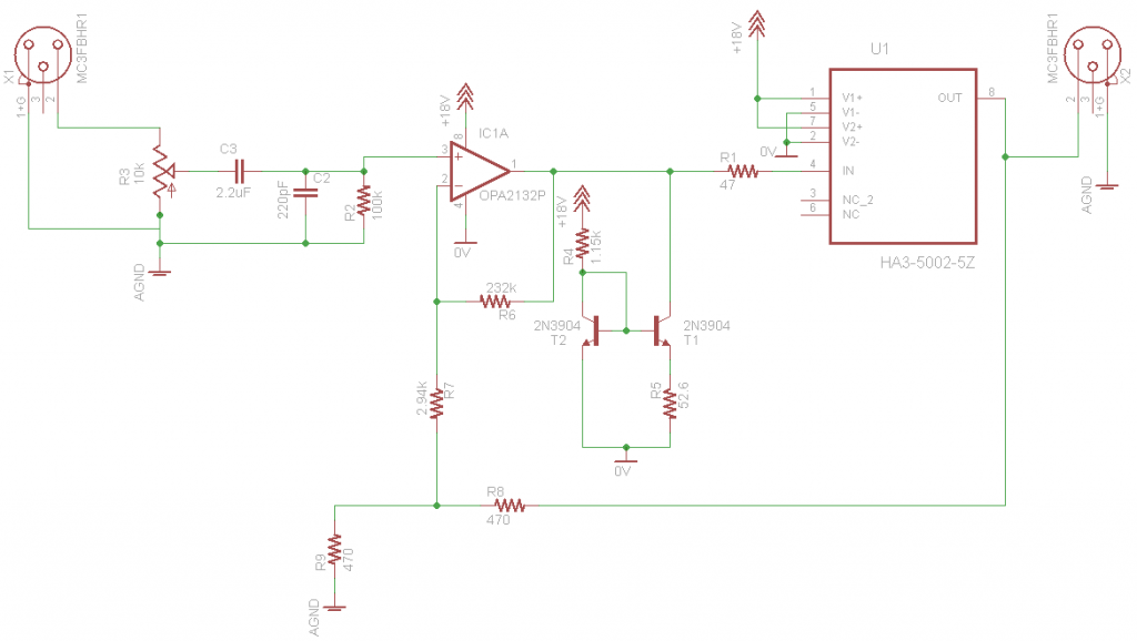
Ok, how's this look for a start?

According to the calculator on Tangent's page (thanks!) Even with R8/R9 = 1 I get gain of nearly two, on account of the local loop? 
 
Also, only have NPNs in the bin, so went with a Widlar source - does that make sense? Set to sink 1.2mA from the OPA2132's output at the moment.
 
Anyway, comments welcome. Nevermind the connectors, just needed something with three pins. I'll be finishing up the power circuit soon, then it's build time!
 
Apr 10, 2013 at 3:10 PM Post #11 of 13
I believe the "inner loop" feedback components are a waste - Walt Jung only showed it once in a monthly column, probably just threw it in on a lark - everything else in the article was brilliant, a must read
 
Walt certainly has written elsewhere that the motivating Otala "TIM", "flat loop gain over audio bandwidth" prescription is simply wrong
 
you can see his 2002 "Op Amp Application" book chapters for free on the Analog.com site -  his audio chapter shows several multiloop line driver circuits - only that one copied from the original article is shown with the inner resistive loop
 
 
with a unity gain buffer much faster than the gain op amp it is trivial to show the claim that the inner feedback loop "improves phase flatness" is false - the result is "the same" with all global feedback up to the tiny fraction of signal loss thru the unity gain buffer at audio  - with the advantage that all of the op amp loop gain also improves the buffer
 
Apr 10, 2013 at 3:34 PM Post #12 of 13
Hmm, I'll have to look into that. Easy enough to leave it out and change global values...
 
Either way, almost ready to start soldering components. Gonna be interesting to see how many of these R and C values I actually have in the bin, it's surprisingly well stocked with certain things, and totally missing others (transformers, inductors, linear regulators). 
 
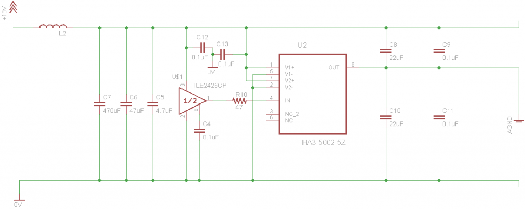
Here's the current power supply, gonna start with the buffered TLE and build up the OPA551 as a backup. Inductor may not exist for real, and the values are somewhat flux right now. Agnd == Vgnd == Input Ground.


Figure I'll stick a couple 0.1uF caps on the V+ inputs of the other chips, just didn't draw it in on the other page.
 
Apr 15, 2013 at 1:44 PM Post #13 of 13
That's a good looking power supply. Instead of the 22uf caps you might like having 470 - 1500uf because it not only helps with the bass but also lets the op amps turn off slowly which takes care of the turn off pop. I use the same ground setup but i am using a dual op amp and both channels for ground(probably overkill) with 1500uf caps on the output but this is battery powered so no noise to filter out. 
 

Users who are viewing this thread

Back
Top