
gavinbirss
Head-Fier
- Joined
- Oct 19, 2001
- Posts
- 83
- Likes
- 11
Hello,
Since seeing both Tangent and Tophu great attempts I felt the need to share my first
design / prototype and will only accept positive critizim.
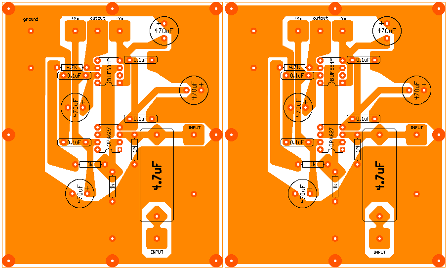
!!! Please note that this image is not actual size. !!!
First glance may reveal that I like thick tracks and lots of ground. My motivation for this
is since you are paying for a full board of copper you may just as well use it instead of
wasting it with the etchant.
Also that I have included two inputs. One that is capped and the other witch is not.
The only phones I used on the circuit are the AKG K 501's and a pair of 32 ohms test
phones. Only at levels you would not put the 32 ohm headphones on your head, the single
BUF634P per channel heats up slightly. (with a 8 ohm pc speaker it does heat up more).
Tophu and others will most likely agree that this circuit is sufficient for the AKG K 501.
During my time with this prototype I discoverd that more ( > +-12,15) DC volts make the
OPA627 and BUF634 come alive. My only concern is that I prever using batteries wich
limits you to moderate supply levels. I use two 12 V 7 Ah lead acid batteries in series
that is split to +12 and -12. (26 V in total on full charge). Later I have used +-15V
from a regulated wall wart. This I then sent into a resistor devidor because the output
of the two regulators did not match.
My other concern is with the level of the signal being amplified. The higher the supply is,
the lower the volume setting to produce the same level on the phones. i.e that you are
amplifying a more attentuated signal the higher the supply voltage. Almost like comparing
a moving coil cartridge to a moving magnet cartridge. (the level difference).
I plan to investigate further into better power supplies(+-15V), biasing the opamp into
Class A and using two BUF634T in parallel and also a preamp / headamp design.
Here is another board that I am going to try.
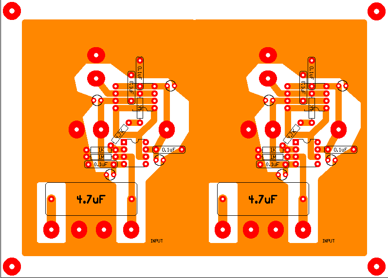
Here I have to BUF634T's in parallel and I would most likely use
them in LOW bandwith mode or solder a wire from the BW pin to
the back side of the package. (which is electrically connected to
V-).
!!! Please note that this image is not actual size. !!!
I have tried the OPA637 and AD797 on this circuit and was unsucsesfull to say the least.
They both produced noise and seemed to be very sensative to the volume pot. Witch is a
cheap dual 50K pot of a precsion lab instrument.
Gavin
Since seeing both Tangent and Tophu great attempts I felt the need to share my first
design / prototype and will only accept positive critizim.
!!! Please note that this image is not actual size. !!!
First glance may reveal that I like thick tracks and lots of ground. My motivation for this
is since you are paying for a full board of copper you may just as well use it instead of
wasting it with the etchant.
Also that I have included two inputs. One that is capped and the other witch is not.
The only phones I used on the circuit are the AKG K 501's and a pair of 32 ohms test
phones. Only at levels you would not put the 32 ohm headphones on your head, the single
BUF634P per channel heats up slightly. (with a 8 ohm pc speaker it does heat up more).
Tophu and others will most likely agree that this circuit is sufficient for the AKG K 501.
During my time with this prototype I discoverd that more ( > +-12,15) DC volts make the
OPA627 and BUF634 come alive. My only concern is that I prever using batteries wich
limits you to moderate supply levels. I use two 12 V 7 Ah lead acid batteries in series
that is split to +12 and -12. (26 V in total on full charge). Later I have used +-15V
from a regulated wall wart. This I then sent into a resistor devidor because the output
of the two regulators did not match.
My other concern is with the level of the signal being amplified. The higher the supply is,
the lower the volume setting to produce the same level on the phones. i.e that you are
amplifying a more attentuated signal the higher the supply voltage. Almost like comparing
a moving coil cartridge to a moving magnet cartridge. (the level difference).
I plan to investigate further into better power supplies(+-15V), biasing the opamp into
Class A and using two BUF634T in parallel and also a preamp / headamp design.
Here is another board that I am going to try.
Here I have to BUF634T's in parallel and I would most likely use
them in LOW bandwith mode or solder a wire from the BW pin to
the back side of the package. (which is electrically connected to
V-).
!!! Please note that this image is not actual size. !!!
I have tried the OPA637 and AD797 on this circuit and was unsucsesfull to say the least.
They both produced noise and seemed to be very sensative to the volume pot. Witch is a
cheap dual 50K pot of a precsion lab instrument.
Gavin


