OPA2227 High current C-moy killer
Feb 6, 2007 at 10:24 AM Thread Starter Post #1 of 25

Nordic

100+ Head-Fier
Joined
Oct 1, 2006
Posts
103
Likes
0
Its so nice to be back....

Bringing you a new toy.
If you have any opa2227 chips around, please try this one, or order some samples from TI.

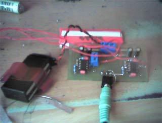
It is an adaption of the headphone amp shown in the datasheet. Using 1 dual opamp per channel with the second acting as a current pump.

The sound is phenomenal...it felt treble light at first, but that is only because so much more haze is removed from hipgh frequency sounds...

I have built alot of headphone amps now, and this gets my vote... for best of my attempts... mine is running of a single 9v battery... if you choose higher gain (you can go to x5 without compensation caps)... you may need 2 batteries.

Circuit is not hotswapable with other opamps as it requires no offset resistor to ground.... well maybe if you cut the trace on pin3 and put your resistor over the cut...

Ok, go, Do it, do it.

opa2227_headphone_circuit.gif


opa2227_headphone_layout.gif


opa2227_headphone.jpg
 
Feb 6, 2007 at 12:09 PM Post #2 of 25
Hmm..nice job. I am getting ready to build mine so I have a question if you don't mind. Will the OPA2227 not work well with Tangent's build?

-EDIT- after a little more research I have found that you do not need the virtual ground, which I assume is what you are talking about, if you are using two batteries instead of one as the batteries can hook directly into the ground without resistors. This is my first build so I am trying to keep it as simple as possible. I see where Tangent talks about using another amp in the way that you do but as of right now I dont fully understand it because I'm still not completely sound about looking at these diagrams.

Nice Job! I am going to try to get some samples from TI in the next week so I might try something like it in the future.
smily_headphones1.gif
 
Feb 6, 2007 at 12:26 PM Post #3 of 25
Nice!! I'll have to give this a try. By the way, what did you use to get your custom PCB and what parameters did you use? I tried ordering my own PCB but I'm completely lost about what kind to order.
 
Feb 6, 2007 at 12:38 PM Post #4 of 25
To be honest I haven't tried... I did try a 2228, but it had the typical bass-lightness normaly associated with bad 2227 circuits...

The double opamps is a step up...

The resistor is described in attachment.
Whatever chip you choose, download the datasheet (google) it will have lots of handy info in.

I made that PCB myself yeah... last bit of photoresist spray in the can... and its the first time I'm happy... only had enough for one side, so I had to draw the traces on the top layer... luckily very easy. Can't believe it took a whole can to figure the stuff out... only used 3 minutes of sunlight exposure...

Also worth looking at is PSR and CMR
I am useing this between my PC and headphones to test now, as my wife takes the ipod to work... there is none of the usual PC noise ... it is clean DAClike sound comming out.

The program you need to open the board and schematic is EAGLE... the demo (light) version will work fine, and is free .. once again google it...

The upload limit is only 25k so get teh full files here
http://www.diyaudio.com/forums/attac...amp=1170766078
 
Feb 6, 2007 at 1:42 PM Post #5 of 25
Okay, I read your post again.

2228 didn't sound good into this or a cmoy ?

Atleast that what I think it is you guys are talking about.

Any modifications needed for a 2228 going into this circuit ?

IIRC the 8 has higher bandwidth.

It just so happens I have 2 2228s sitting around doing nothing.
 
Feb 6, 2007 at 2:10 PM Post #6 of 25
2228 did not sound nice in cmoy... It is not unity gain stable...to use it with this circuit you will have to parallel a small cap 2p2 to 20p with the feedback resistor...

I used 2228 in my VSPS phono amps as drop in replacements, where I am very happy with it.
opa2227_headphone2.jpg
 
Feb 6, 2007 at 3:17 PM Post #8 of 25
Your schematic is confuzzling me.

Like there is no input 2 for the left channel yet clearly on the board, input 2 does go the left channel. Same goes for some of the power ones.

I know it's going to ground and well yeah, makes sense, just sort of confusing at first for people like me.
 
Feb 6, 2007 at 4:08 PM Post #9 of 25
inputs are infront of R1 and R5

V+ and V- is marked on the board in red and blue... gnd is between them... shared... useing a 9V cell. you can connect it from + to -
 
Feb 6, 2007 at 5:00 PM Post #10 of 25
Well I know that, just, never mind I can't even see why I'm saying about it.

I'm was just commenting where you've put the input and power, I'll call them bubbles on the schematic. It was just confusing me at first. Now that I've bothered to get the brain in gear it all makes sense.
biggrin.gif
 
Feb 6, 2007 at 5:33 PM Post #11 of 25
how does it perform with ad8397? May be more difficult to use, though
 
Feb 6, 2007 at 8:06 PM Post #12 of 25
ad8397 needs to be used at gain = or > 2...

Otherwise the layout should work.. it wouldn't need a current pump though, they can do 310 mA peak into 32 Ω on ±12 V supplies while maintaining
−80 dBc SFDR
 
Feb 7, 2007 at 1:10 AM Post #13 of 25
Quote:

Originally Posted by j4cbo /img/forum/go_quote.gif
Reminiscent of the Apheared 47...

Any particular reason for the inverting topology?


I, too would like to know the purpose of inverted input in this design. Seems counter productive somehow. Or maybe I'm just being closed minded here, in need of enlightenment....
 
Feb 7, 2007 at 2:55 AM Post #14 of 25
8397 works at unity gain provided you bypass properly and depending on a few other conditions, or do you mean in this design it wouldn't work?

I was just curious about how it'd do in the circuit, just for the heck of it. I'm well aware that it already possesses high current output, but that doesn't necessarily mean this design wouldn't be suitable for it *shrug*. It looks as though this design has some other advantages, no?
 
Feb 7, 2007 at 7:57 AM Post #15 of 25
I would say you could try it... look up the datasheet to see what the max current is those chips can take on the input... The second set of resitors on the output are to protect the input stage of the next opamp stage. I have not adjusted them yet from unity gain RX = VS/20mA – RSOURCE
So at 2x gain , 100R should be enough protection. You need to apply the same concept with the appropriate numbers for your chip.

If it needs a resistor from +input pin to ground, cut the long trace from pin 2 and solder it over the cut.

Regarding the inverted setup....
It is the most common way to use an opamp... and also the favoured one in the datasheet...
I read too many complaints from people doing their own thing, that the opa2227 is bass shy and shrill, when it is actualy the exact oposite in this circuit...

....some other factors include negative feedback, high input impendance (no current flows through the chip)...

probably noise factors too
Noise in Inverting Gain Configuration:
Eo²= (1+R2/R1+Rs)² x en² + e1² + e2² + (in x R2)² + es²

Non- inverting
Eo²=(1+R2/R1)² x en² + e1² + e2² + (in x R2)² + es² + (in+Rs)² x (1+R2/R1)²
 

Users who are viewing this thread

Back
Top