


You are using an out of date browser. It may not display this or other websites correctly.
You should upgrade or use an alternative browser.
You should upgrade or use an alternative browser.
New Portable Amp - "Pocket Class A" by xrk971 - now available as complete PCB
- Thread starter stellarelephant
- Start date
xrk971
Member of the Trade: XRKAudio
Probably more like $1425 ... or $2425

You are pretty good with pricing!
DBaldock9
Headphoneus Supremus
I've got a couple of questions about the naming convention on the schematics (specifically the DCA) on your web store.
A few of the capacitors have labels with letter suffixes:
C101
C101A - C101D
C102
C102A - C102D
C111
C111A - C111B
C112
C112A - C112B
C113
C113A
C114
C114A
Are the ones with letters optional, or do all of the capacitors need to be installed?
The Values given for some of those capacitors isn't listed in uF.
For example - what size / values should I try to buy for these?
C101A C22/10 C22.5B10
C101B C27/17 C27.5B17
Thanks,
David Baldock
xrk971
Member of the Trade: XRKAudio
Those designations refer to all the optional pad sizes for different caps. This board was made for the DIY cap roller who likes to try different caps. They come in different lead spacings.
The main thing to know is that the input cap should be at least 4.7uF film or electrolytic. If electrolytic put positive facing the JFET.
The output cap should be at least 2200uF electrolytic. You can bypass with a film cap of several sizes.
So to get a working amp, I would suggest a 4.7uF MKP axial or radial film cap with lead spacing fitting one of those spaces.
On output, use a 2200uF radial electrolytic. Add a 2.2uF MKP or MKS cap and you are good. Sometimes no film bypass needed. Some people think that sounds better actually.
xrk971
Member of the Trade: XRKAudio
I think you are overthinking this. You might want to just get a board and start building. Nothing is locked in concrete and you can swap parts to your hearts content as the copper is 2oz thick and held down with lots of vias on 2mm board. It’s very durable and can withstand desoldering. Build one board and listen to it. If you like it, build another and make your balanced drive amp then. It’s an easy amp to make and get working and the sound is fantastic. You know the sound - like the Pocket Class A but lots more power.
Juat start building and trying it out and if you need stuff, Mouser is in Texas and ships you stuff the next day or two. That will answer many more questions than trying to get it all figured out on paper first.")
Juat start building and trying it out and if you need stuff, Mouser is in Texas and ships you stuff the next day or two. That will answer many more questions than trying to get it all figured out on paper first.
xrk971
Member of the Trade: XRKAudio
Hi David,
You might want to start participating in the GB thread - that’s where the community asks questions and share answers. That way, everyone benefits from the same questions you ask. There’s a lot of good info in the thread - like matching JFETs or what DC-DC converter to use, or what caps work well, etc. the question you just asked about optional caps was asked in post 22 for example.
http://www.diyaudio.com/forums/head...op-class-dca-headphone-amp-3.html#post5435639
Here is main thread:
http://www.diyaudio.com/forums/headphone-systems/322638-xrk971-desktop-class-dca-headphone-amp.html
Last edited:
DBaldock9
Headphoneus Supremus
Thanks!
I see that your web store lists "Matched FETs for DCA" - are those still available?
I see that your web store lists "Matched FETs for DCA" - are those still available?
xrk971
Member of the Trade: XRKAudio
Yes, I have matched FETs for DCA. However my basement just got flooded so finding things may take me a few days.
DBaldock9
Headphoneus Supremus
Yes, I have matched FETs for DCA. However my basement just got flooded so finding things may take me a few days.


MyPants
100+ Head-Fier
crap is getting hardcore in here. I like it.
xrk971
Member of the Trade: XRKAudio
Mypants,
Sorry, don't understand your last post is referring to?
Sorry, don't understand your last post is referring to?
DBaldock9
Headphoneus Supremus
Working on the logistics of assembling an integrated Amp (Balanced & Un-Balanced) / Selector Switch unit for headphones.
It will have Balanced & Un-Balanced inputs for line level, and headphone level signals, and be able to switch them through to DCA Amps, and/or Balanced & Un-Balanced output jacks.
There will have to be some smarts to the relay control switching, to keep from sending a Balanced signal to an Un-Balanced load.
Here's a block diagram of what needs to be inside the chassis -
.

.
xrk971
Member of the Trade: XRKAudio
Dbaldock9,
I think I have a much simpler passive solution for you. It's detailed over on DIYA thread for DCA, but I will repeat here:
You might be able to do this via passive "switching" on the input/output TRS or XLR jacks.
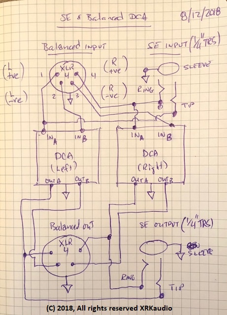
Here is one approach to try... when using balanced, require a 4 pin XLR input jack to be used and 4 pin XLR output (to phones to be used) and wire accordingly.
When desiring to use unbalanced input and unbalanced output, use 3.5mm or 1/4in TRS input jack with right and left connected to only the +ve side of respective left DCA, and right DCA board. Correspondingly, the DCA board output on +ve side goes to right/left of TRS output jack. So basically, the negative (-ve) side of each DCA board is left unused when in unbalanced mode.
See attached schematic. Easy peasy... You could in fact power both balanced and unbalanced headphones simultaneously as amp has plenty of power to spare assuming impedance is not too low on either can. Since everything is cap-coupled, there is no fear of DC imbalance blowing something out.
Cheers,
X
I think I have a much simpler passive solution for you. It's detailed over on DIYA thread for DCA, but I will repeat here:
You might be able to do this via passive "switching" on the input/output TRS or XLR jacks.
Here is one approach to try... when using balanced, require a 4 pin XLR input jack to be used and 4 pin XLR output (to phones to be used) and wire accordingly.
When desiring to use unbalanced input and unbalanced output, use 3.5mm or 1/4in TRS input jack with right and left connected to only the +ve side of respective left DCA, and right DCA board. Correspondingly, the DCA board output on +ve side goes to right/left of TRS output jack. So basically, the negative (-ve) side of each DCA board is left unused when in unbalanced mode.
See attached schematic. Easy peasy... You could in fact power both balanced and unbalanced headphones simultaneously as amp has plenty of power to spare assuming impedance is not too low on either can. Since everything is cap-coupled, there is no fear of DC imbalance blowing something out.
Cheers,
X
DBaldock9
Headphoneus Supremus
I agree!
Looks like they've made 4 posts in the Headphones For Sale thread, and then a "." in a bunch of other threads.
Wonder what that's all about?
Users who are viewing this thread
Total: 4 (members: 0, guests: 4)
