


tomb
Member of the Trade: Beezar.com
- Joined
- Mar 1, 2006
- Posts
- 10,891
- Likes
- 1,053
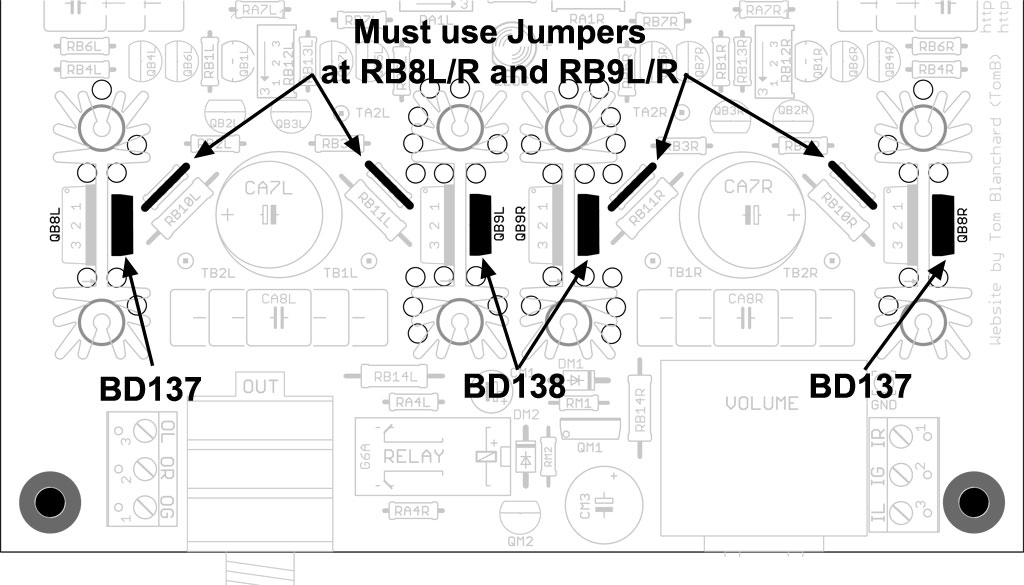
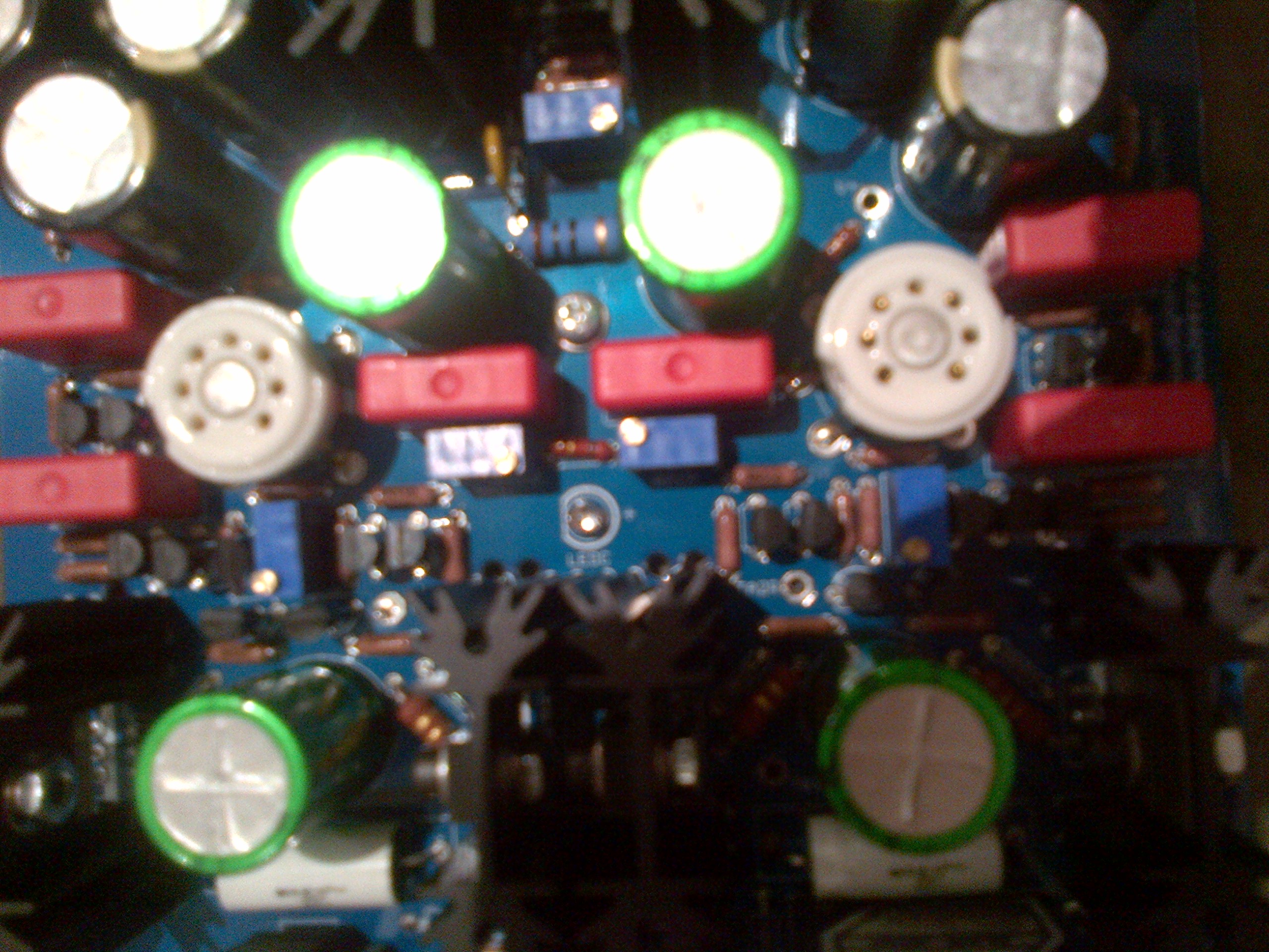
You need to go over every transistor solder joint in that left channel very carefully. Looking at QB2L, I can't believe the leads are not touching. It appears that the transistor is bent sideways so far to the headphone jack side that the far edge of the transistor is over the center pad. If the leads are bent sideways that far, chances are they're touching. There's also a solder blob on QB3R that looks big enough to cover both pads. Make certain you don't have any solder blobs touching other pads and inspect all of the transistor leads to ensure that you don't have anything touching. Are the pads clean and leads secure on the heat sinked transistors?
Can you get us similar pics of the bottom of the PCB? I'm beginning to think it's some messy solder joint somewhere that's shorting out. We can't confirm the transistors from these pics, but if you've double-checked that none are in the wrong place and you've already checked and measured the resistors, then that leaves a short somewhere as the issue - touching lead, solder blob out of place, etc.
EDIT: Just an FYI, but I'm afraid you're going to have problems casing it up unless you change the mounting of those Vitamin Q's - they appear to be too high toward the center. You should refer to this detail from the MiniMAX website:

This image is a little ideal, but there's a scale PDF link below on that page (http://www.diyforums.org/MiniMAX/MiniMAXvitQ.php) that has it drawn exactly:
http://www.diyforums.org/MiniMAX/vitQ/VitQinstall.pdf
The key is that I don't think you can get the height low enough (without shorting out the leads) unless that tall lead is bent slightly back under the VitQ and soldered into one of the interior holes - not the outside one.
Can you get us similar pics of the bottom of the PCB? I'm beginning to think it's some messy solder joint somewhere that's shorting out. We can't confirm the transistors from these pics, but if you've double-checked that none are in the wrong place and you've already checked and measured the resistors, then that leaves a short somewhere as the issue - touching lead, solder blob out of place, etc.
EDIT: Just an FYI, but I'm afraid you're going to have problems casing it up unless you change the mounting of those Vitamin Q's - they appear to be too high toward the center. You should refer to this detail from the MiniMAX website:
This image is a little ideal, but there's a scale PDF link below on that page (http://www.diyforums.org/MiniMAX/MiniMAXvitQ.php) that has it drawn exactly:
http://www.diyforums.org/MiniMAX/vitQ/VitQinstall.pdf
The key is that I don't think you can get the height low enough (without shorting out the leads) unless that tall lead is bent slightly back under the VitQ and soldered into one of the interior holes - not the outside one.


