New Millett Hybrid MiniMAX (what happened to this thread?)
Mar 24, 2010 at 8:13 PM Post #1,426 of 1,948
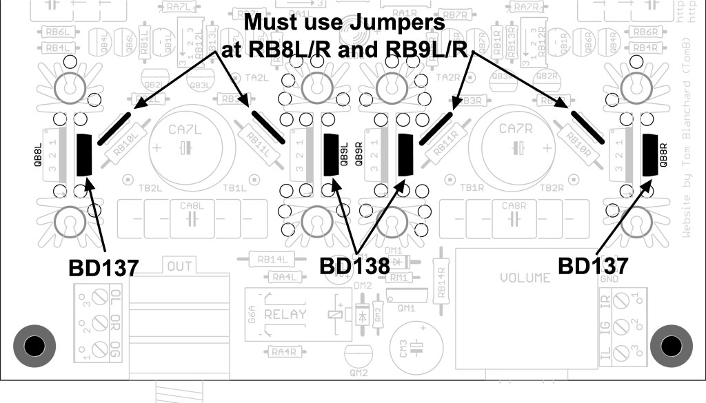
Hello everybody. This is my first question on this forum to complete my first MiniMAX purchased from Beezer: When using the Toshiba 2SC3422/2SA1359 output transistors, how do you create a jumper connection for RB8L/R and RB9L/R? Is this just a piece of wire? If so, what gauge and what kind (solid, stranded) should I use? Thanks in advance for any answers to this.
 
Mar 25, 2010 at 12:07 PM Post #1,432 of 1,948
Quote:

Originally Posted by BlingBlingDr /img/forum/go_quote.gif
Hey. Is there a difference between these two ways of soldering the VitQs in terms of performance? Is either one better than the other?

Notice how the longer lead is soldered through a different hole in each one.


No, there is no difference in terms of performance. However, I prefer the arrangement in the 2nd pic (not saying it's right or wrong, though). It may be preferrable to get as much of the lead as far away from the heat sink as possible. These things will arc under certain conditions. If there is a portion of the heat sink where the anodization has worn off and if the insulation between transistor and heat sink is not optimum, then it may be possible for the Vitamin Q to arc from those leads over to the heat sink.

Granted, that's a lot of "if's", but I have seen the older Russian K42's arc against the top of the case if they weren't insulated. Of course, in that instance the case was grounded and the heat sinks aren't. So, the chances are probably very slim. If you can use one of the closer in pads - do so. If it's a hassle to do that, chances are you'll still be fine.
smily_headphones1.gif
 
Mar 25, 2010 at 8:19 PM Post #1,434 of 1,948
Quote:

Originally Posted by radicalrev /img/forum/go_quote.gif
Just got my Minimax from a Head-Fi member a couple of days ago. The minimax doesn't have the tube light (led) and was wondering if I could still add them?

Any DIYer in the Los Angeles area care to help me?
smily_headphones1.gif


It's possible, but it may not be the easiest trick in the world.
wink.gif
I'm assuming that the reason the LED's are not there is because the tube sockets weren't drilled. You see, the tube sockets have a center pin that completely fills the center of the socket where you would want to have the LED - or at least to shine the LED through. Normal procedure is to drill the center pins out, then glue the socket halves back together. (See reference in the SSMH build thread in my signature - the procedure is the same.) This becomes more difficult when the sockets are already soldered into the PCB, but it can be done.
 
Mar 25, 2010 at 9:54 PM Post #1,435 of 1,948
I'm having a lot of trouble soldering the Emerson Tip Jacks, mainly because I'm not sure what the orientation of my tinned wires should be in relation to the silver contacts that stick out from the rear of the jacks. Should my wires be wrapped around these contacts somehow? (If so, then I'm guessing they shouldn't be tinned.) Should they run parallel to the contacts? Or, should they be connected at a 90 degree angle somehow to the end of the contacts where there are those little nubs? The relevant connections shown on the MiniMAX site are covered with heat shrink, so I can't see what went on there. I'm just not getting this....
 
Mar 25, 2010 at 11:05 PM Post #1,436 of 1,948
Quote:

Originally Posted by rbarth /img/forum/go_quote.gif
I'm having a lot of trouble soldering the Emerson Tip Jacks, mainly because I'm not sure what the orientation of my tinned wires should be in relation to the silver contacts that stick out from the rear of the jacks. Should my wires be wrapped around these contacts somehow? (If so, then I'm guessing they shouldn't be tinned.) Should they run parallel to the contacts? Or, should they be connected at a 90 degree angle somehow to the end of the contacts where there are those little nubs? The relevant connections shown on the MiniMAX site are covered with heat shrink, so I can't see what went on there. I'm just not getting this....


Generally, you should have about one to two turns of the wire wrapped around the tip jack contact. Orient this so that the continuation of the wire lead ends up on the bottom of the tip jack contact and is pointed down. This will keep you from having to bend the entire assembly down by hand (and perhaps cracking the solder joint) to clear the PS heat sink.

The solder joint should run the span of the bare lead that's wrapped around the tip jack contact. That keeps the connection strong in the face of a lot of stress when you assemble/disassemble the back plate and case. Make sure you heat shrink each connection, though, because the leads are very close to the PS heat sink.
smily_headphones1.gif
 
Mar 25, 2010 at 11:21 PM Post #1,437 of 1,948
Quote:

Originally Posted by tomb /img/forum/go_quote.gif
Generally, you should have about one to two turns of the wire wrapped around the tip jack contact. Orient this so that the continuation of the wire lead ends up on the bottom of the tip jack contact and is pointed down. This will keep you from having to bend the entire assembly down by hand (and perhaps cracking the solder joint) to clear the PS heat sink.

The solder joint should run the span of the bare lead that's wrapped around the tip jack contact. That keeps the connection strong in the face of a lot of stress when you assemble/disassemble the back plate and case. Make sure you heat shrink each connection, though, because the leads are very close to the PS heat sink.
smily_headphones1.gif


Thanks for your response, Tom. It was very clear and very, very helpful. I guess what threw me off was that I thought that, except for the volume pot ground wire, all wiring connections should be tinned prior to soldering. Clearly that's not the case with the tip jack connections.
 
Mar 26, 2010 at 12:08 AM Post #1,438 of 1,948
Quote:

Originally Posted by rbarth /img/forum/go_quote.gif
Thanks for your response, Tom. It was very clear and very, very helpful. I guess what threw me off was that I thought that, except for the volume pot ground wire, all wiring connections should be tinned prior to soldering. Clearly that's not the case with the tip jack connections.


Actually, I still tin them ... but lightly.
wink.gif
Seriously, a small bit of tinning (very small) and multi-strand wire can behave like solid wire.

If you use too much, though, it could get frustrating because it would be impossible to remove - you just have to cut the wire and try again. So, please - only do what makes you feel comfortable.
smily_headphones1.gif
 
Mar 27, 2010 at 5:39 AM Post #1,439 of 1,948
Just finished my first MiniMAX, turned it on and no explosions (yet). BUT: Power supply voltage reads 30.3V and spinning the RR3 trimmer screw in either direction does not change this reading. Trimmers for the tubes and DB are working fine, I can lower and increase the voltages for them. What could be wrong? How do I diagnose/fix this problem?
 
Mar 27, 2010 at 8:04 AM Post #1,440 of 1,948
Quote:

Originally Posted by rbarth /img/forum/go_quote.gif
Just finished my first MiniMAX, turned it on and no explosions (yet). BUT: Power supply voltage reads 30.3V and spinning the RR3 trimmer screw in either direction does not change this reading. Trimmers for the tubes and DB are working fine, I can lower and increase the voltages for them. What could be wrong? How do I diagnose/fix this problem?


See if you can measure a resistance difference in RR3 when you turn it (amp off!) - measure the two pins underneath the PCB that are not connected, turn the screw about a half dozen times in either direction and measure the pins afterward each time.

If that seems to work, give us some pics of the PS section. Used to, this issue could've been a result of turning the small cap around in the PS, but we've changed the parts since that time, so I'm a bit unsure what it might be if the trimmer checks out. 30.3VDC is just about what you should get if there's no regulation whatsoever, so it could be the LM317, too.

As I said, give us some pics if the trimmer checks out OK.
smily_headphones1.gif
 

Users who are viewing this thread

Back
Top