


Oberst Oswald
100+ Head-Fier
- Joined
- Jul 5, 2008
- Posts
- 127
- Likes
- 10
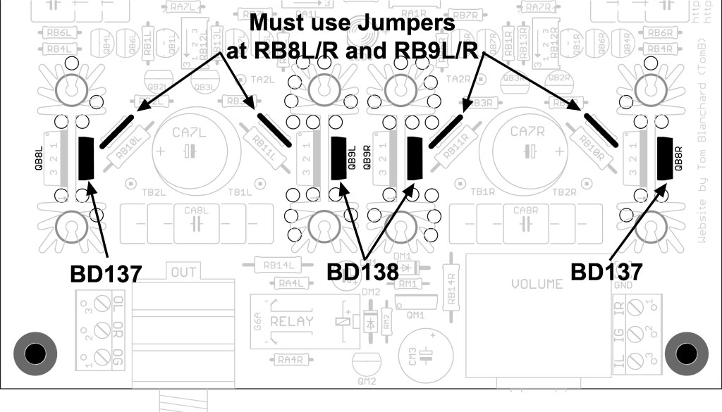
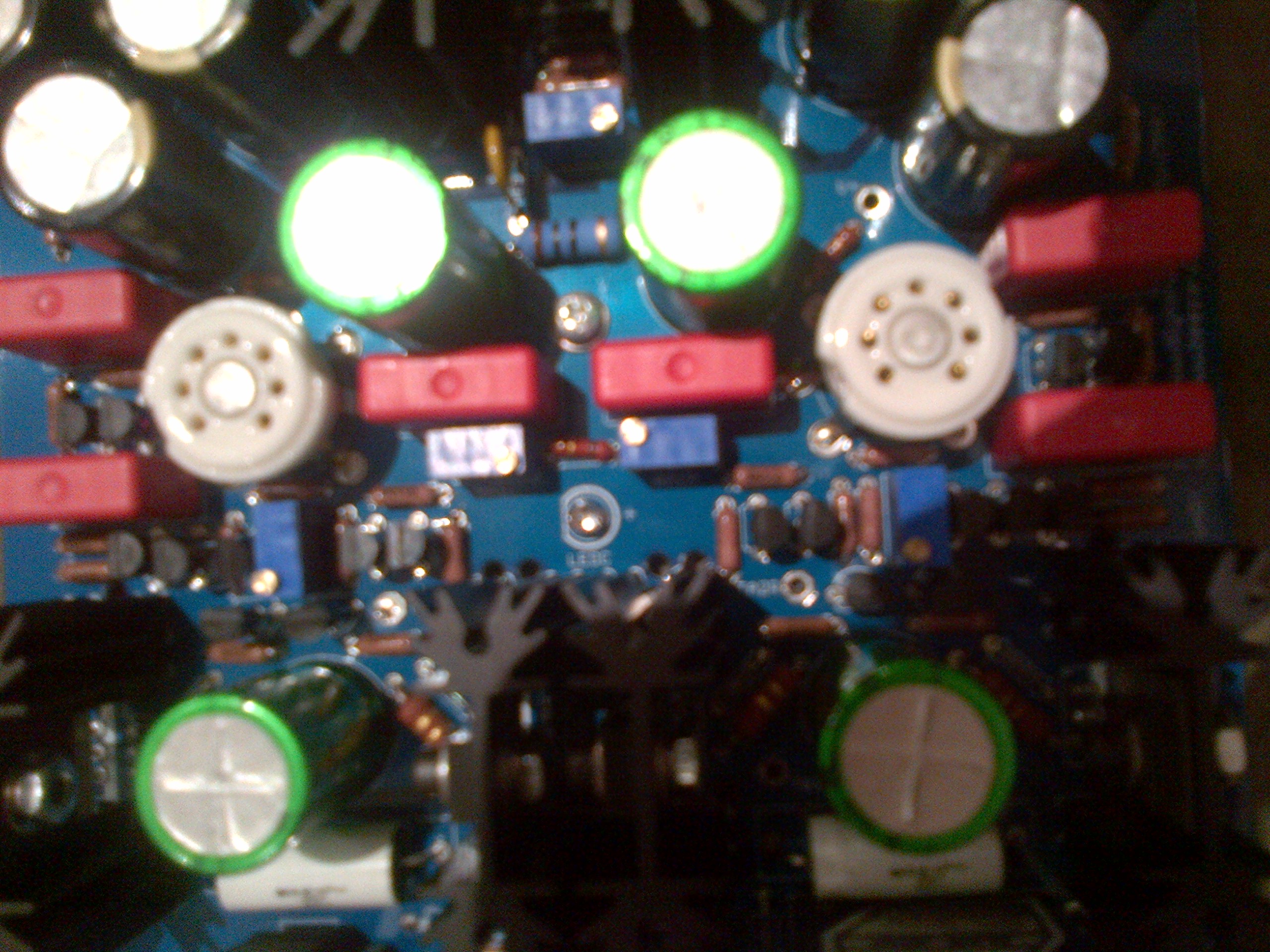
Have a problem... DB Bias. I turned the pots clockwise until I heard the click and took a reading: 1.7mV. Seemed safe so I set the power supply voltage to 27v. Set Tube Bias to Left 13.57, Right 13.63. All is well...so I thought When back to adjust the DB Bias to 110mV but I could not get the pots to adjust properly to get the mV climbing. Smelled smoke and shut of fast. Too late...think I burned out the QB1R transistor because now the board lights up for a few seconds and than slowly dims off. Now I can buy new transistors etc but I don't know whats wrong with why I can't get the pots to adjust. I have a good camera but I don't know how to post pictures to show you my build. Pretty sure I did a good job building it and triple+ checked everything but I'm hopelessly lost now on where the problem is and what I need to do or buy to repair it. Thanks in advance for all help.


