New DIY Altoids Tin Amp - The Pocket Class A "Wintergreen Handwarmer" by xrk971
Apr 9, 2017 at 10:57 AM Post #241 of 468
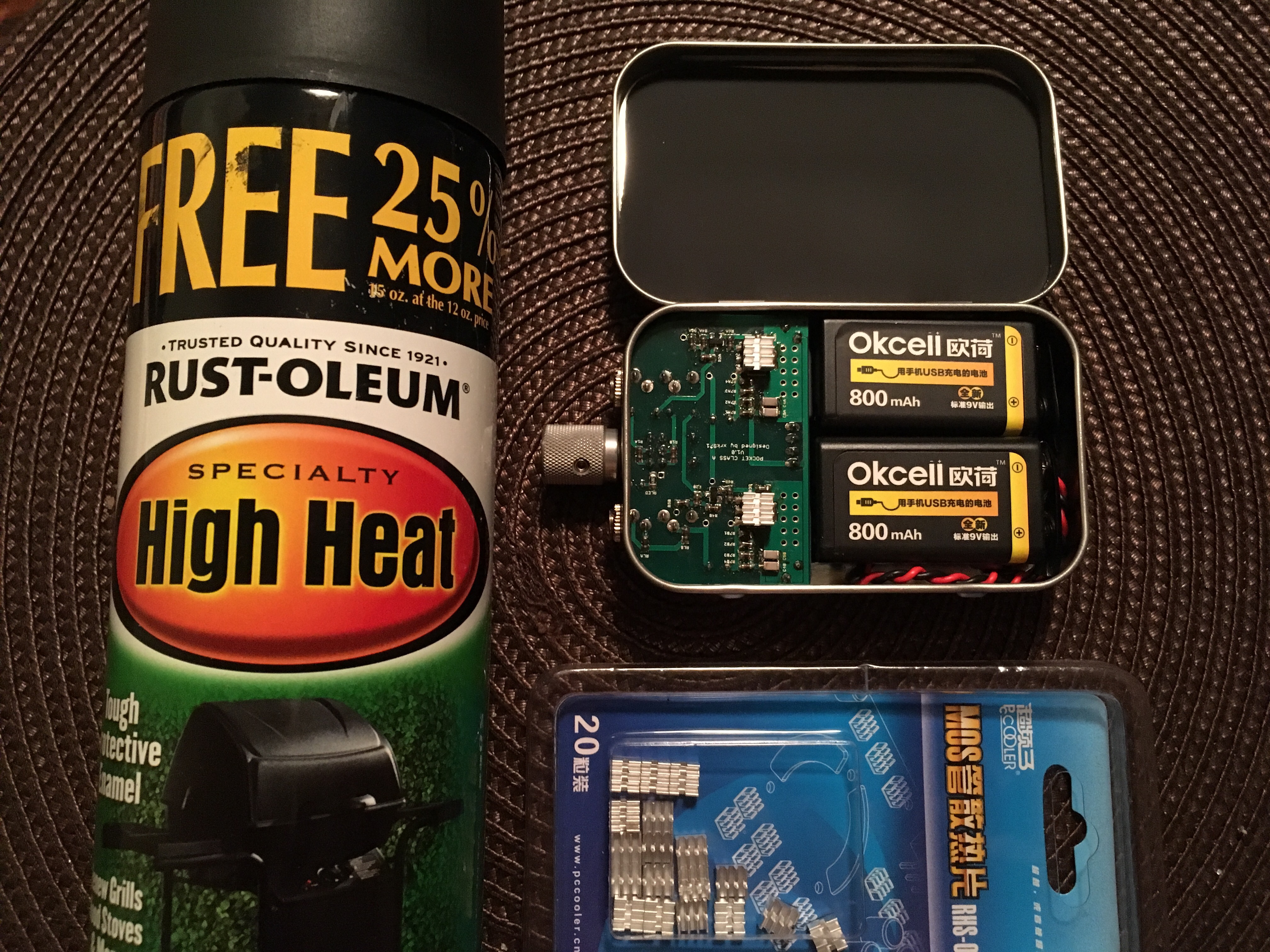
Yes, but I have to warn folks that fhe qualify control on this brand is marginal. When fhey work, they work well. However be prepared for duds. Failure rate is maybe 30% to 40% out of the box. I have sent 3 boxes back. Amazon is nice for this. I get ones with charger for $21 with 4 batteries.


Thank you for the feedback

I think I'll go with Tenergy 9V 600ma ones because I've had good experience with their Centura AA for my DSLR external flashes, tho not Eneloop grade but close
 
Apr 9, 2017 at 4:28 PM Post #242 of 468
Could you elaborate a bit more on how to tune the bias and output capacitorsfor lower impedance headphones?
[Nevermind, went back a few pages and found the post about capacitance. How should I adjust the bias current though? / Do I need to?]
I would be looking to use it with ~35-50 ohm headphones. May also use it with some IEMs for the heck of it, and the lowest of my bunch of IEMs would be around 12ohm.
(Also, how do you plan to fit 3 capacitors in the space allotted for the one output capacitor???)


What caps do you have on the power rails there (dimensions wise)? Wondering if I can get away with some 25mm tall caps and position them how you have yours.


I am using 10x20mm 1000uF 25V Nichicon KA audio caps. Biggest reported to fit are 13x20mm. They can be mounted symmetrically too, as X has done. He has a pic a few posts back. For my next build I plan to try some Panasonics, either 1500uF FR or 2000uF HD.

Bias is tuned via R4 resistor value. We just discussed this recently on the DIYA thread. I used the "stock" 33R value, which yielded 55mA bias, and it sounds great with my 50 and 32 ohm cans. I might tweak it a bit and try 47R for my second build, as I'm told it gives a bit more slam for low impedance cans, and lowers THD (in exchange for more heat and shorter battery life). The sound and dynamics are already incredible as is though!
 
Apr 9, 2017 at 5:51 PM Post #243 of 468
It's very low level -108dB visible on an FFT with switcher I was using. I could not hear it - would not have known if I hadn't measured it. It looks like this.


I used a CRCRC with 2.2mF and 0.33R to clean it up.

If you can't hear it - don't worry be happy!
smily_headphones1.gif

I have a pretty nice ECHO 24/96 firewire soundcard.  I'd like to learn to make FFT measurements like this...  It would be cool to see what differences, if any, I'd measure from tweaking bias or swapping caps.  I could also see how quiet or noisy my batteries are.  X, are you using the free or paid version of Rightmark RMAA?  I normally use my Mac for audio stuff, but since this is Windows only software, I'll have to dig out my grisly old XP laptop
confused_face.gif
, or find an equivalent Mac program.  I recall you talking briefly about a "loopback" measurement at DIYA a while back.  I guess my that would be my first step.  Hopefully the program will perform the calibration itself so I won't have to too much crazy math...
 
Apr 10, 2017 at 9:08 AM Post #244 of 468
I am using 10x20mm 1000uF 25V Nichicon KA audio caps. Biggest reported to fit are 13x20mm. They can be mounted symmetrically too, as X has done. He has a pic a few posts back. For my next build I plan to try some Panasonics, either 1500uF FR or 2000uF HD.

Bias is tuned via R4 resistor value. We just discussed this recently on the DIYA thread. I used the "stock" 33R value, which yielded 55mA bias, and it sounds great with my 50 and 32 ohm cans. I might tweak it a bit and try 47R for my second build, as I'm told it gives a bit more slam for low impedance cans, and lowers THD (in exchange for more heat and shorter battery life). The sound and dynamics are already incredible as is though!

funny that, i was thinking of chucking the 1500uf FRs on output :)
no idea if it'll still fit in the tin, but might as well see what sounds good then go about trying to fit it into a case
 
Apr 11, 2017 at 2:02 AM Post #246 of 468
The max voltage on the BF862 JFET is 20v. Although there is a 1k resistor that will drop the rail down by maybe 5 or 6v so should be fine. Let me run a simulation with 24v and see where it is at.

The bigger concern is heat dissipation. You would be burning 1200mW on the four R4 resistors vs 500mW at the lower voltage. The MOSFETs would also be burning off quite a bit of heat more. You could press the SMT side against a soft thick silicone heatsink pad and clamp it tonremoce heat faster and could then drive it hard.
 
Apr 13, 2017 at 2:27 AM Post #248 of 468
I am testing my desktop version of the pocket amp right now with a 19v SMPS followed by a Linear Tecnolgies LT1963A low-dropout, low noise regulator, I can adjust the output to 18.0v exactly which gives me 113mA bias current in the IRF610 MOSFETs. I tested it with a 33ohm load resistor and then paralleled my 250ohm DT770 with it in order to listen to the effect of a combined circa 30ohm load (combined with 270ohm load resistor on-board). It sounds very good - excellent bass extension as I am running 2x1000uF 16v OSCONs on the output with 1uF Wima bypass and 10uF electrolytic with 0.1uF MKT bypass on the inputs. I installed a rather large 10,000uF 25v Rubycon caps on the power rail to smooth out the linear regulated PSU even further. There is no audible noise or hum from the PSU when using a high quality SMPS from a major brand (HP). This amp is ready to go in a case and will make an excellent fairly compact desktop amp with an easy to use external 19v laptop brick power supply.

 
Apr 13, 2017 at 9:08 AM Post #250 of 468
You mean the one in above post? That one is from eBay. Look for ultra low noise linear power supplies for DACs and you will see many similar ones.
 
Apr 21, 2017 at 5:11 PM Post #251 of 468
Here's my collection. The two on the left use unmatched trannies; the right two use matched. They all use Wima 2.2uF, and Silmic II 4.7uF/25V C1's, and Nichi UHE 1000uF/16V at C3.

I will keep the last two, and plan to send the first two on to new owners eventually.


This one uses Nichi 470uF/16V UKA's and Wima 1uF for C2 to drive low Z 'phones.


Silmic 100uF/16V and Wima 1uF here at C2 for high Z 'phones.


This is my NHB unit for low Z 'phones. It uses 470uF/16V Silmic's with 4.7uF Wima's at C2. Since the Silmics are so large .......


.......... I had to mount the Wima's on the SMD side. Because they are thicker, the tin lid doesn't close all the way at front, but does latch at the back.


This is my NHB build for hi Z 'phones, and uses 47uF/16V Silmics and .47uF Wima's at C2.

FWIW, I much prefer the sound of the Silmic's to the UKA's. The UKA's sound thin to me, with a forward midrange that can sound a bit 'shouty'. The Silmic's are much smoother, but still give plenty of detail.

Sorry for the poor pic's from my old camera. My photog skills aren't that great either.
 
Last edited:
Apr 21, 2017 at 7:03 PM Post #252 of 468
Funch,
Thanks for sharing your collection of amps. I am able to solder the 2.2uF Wima's on SMT side and still get lid to close. Is your 4.7uF Wima same size? The trick is to cut the pins of the other cap as close as possible and lay Wima touching the pins. Bend Wima legs 90 deg so they can join protruding solder dab from cap legs coming through. I have to get me some 470uF Silmics. Those are huge! :)

Here is closeup of one my NHB's with Wima's on SMT side at C2 and lid still closes.


Here is dual 1000uF OSCONs for low impedance cans.


Here is a combo with 1000uF OSCONs and 470uF Nichicon AK's for a balanced system:
 

Users who are viewing this thread

Back
Top