New DIY Altoids Tin Amp - The Pocket Class A "Wintergreen Handwarmer" by xrk971
Mar 27, 2017 at 5:07 PM Post #166 of 468

Very cool. I will look into some diy plans because I'm not seeing anything using the same source and headphones.

I thought about making something like this, and using 3.5mm splitter from the source to each amp, which would go into a/b.

https://www.google.com/url?sa=t&source=web&rct=j&url=https://www.amazon.com/Sescom-SES-IPOD-AB-Stereo-MP3-Player/dp/B005TE7GP4&ved=0ahUKEwjStqixxvfSAhWr6oMKHa-RBVgQFgg7MAA&usg=AFQjCNHCPlZyoVp_cI5Zq-GuxPwLbpTJ0A&sig2=9FWeyVhSYyKQNNjHRxhitA


I can post the schematic later tonight. It's pretty simple - signal path source input (L/R) goes to common pin on relay 1 and signal on n/c pins goes to amp A input. Amp A output returns to n/c pins on relay 2 and common of relay 2 goes to headphone out. The n/o pins on relay 1 are connected to amp B input and amp B output goes to n/o pins of relay 2. Both relay coils are connected to common signal from momentary on off switch. I use a $0.40 dc step up converter MT306 from China to make 12v from 9v carbon or alkaline cell. System is normallly routed through amp A with no power applied to relay. Pushing switch flips both relays to route signal from source through amp B and back out to headphones. Instantly. Click. When you level match amps you almost can't tell it switches in mid stream. If it weren't for the click of the relays it would be almost imperceptible.
 
Mar 27, 2017 at 5:14 PM Post #167 of 468
When will the second one be available? I'm not enthusiastic about plucking at SMD resistors :wink:


Sorry but I don't see a through hole version of this coming along. First, it would be much bigger and have a hard time fitting in a mint tin. Secondly, member BabyDontHertzMe, the layout artist, has been MIA for some time now. I hope he is ok. He is in South Africa and if anyone knows of his whereabouts let him know we hope he is OK.

I can't do layouts in CAD - just hand made one off stuff.

If you have a hard time with SMT's I can sell you a board with all SMTs preinstalled. Just PM me.
 
Mar 27, 2017 at 10:17 PM Post #168 of 468
Sorry but I don't see a through hole version of this coming along. First, it would be much bigger and have a hard time fitting in a mint tin.

 
All-thru-hole will be a lot more diy-able for many people, though.
Maybe a desktop version that is powered off USB? Losing the batteries can yield quite a bit of extra room, the thru-hole board can probably still fit into a tin. Many might (eventually) want to upgrade the input and output caps, having extra room available provides more upgrading possibilities as well.
 
Mar 29, 2017 at 1:22 PM Post #170 of 468
Audiocats, the SMT work wasn't as hard as I expected, although I did have to buy a $20 soldering iron with a small tip and some tweezers to do it. I may get a magnifier to use for my next board too. If you can get past the SMT part, it would be possible to use much bigger caps with this board if you are not constrained by a mint tin. If you had a truly huge cap, you could even install it from the opposite side of the board from where they were planned to go. They'd sit above the SMT components. Lots of room there.
 
Mar 29, 2017 at 1:46 PM Post #171 of 468
StellarElephant has a good point. It's not that hard.  In fact, I prefer to do SMT work now over through hole whenever I can because it is faster, neater, tighter layout.  Faster?  Yes, you only work on one side of the board and there is no bending leads, fitting leads, soldering leads, trimming leads.
 
Even faster than a soldering iron, buy a small syringe of SMT solder paste (consistency of thick toothpaste), use the included hypodermic needle to apply a small dab on each SMT pad.  Place the SMT part in place.  Put board on a small old frypan (junk one you wont't cook food in ever again), put on stove or hotplate medium heat for 2 minutes until paste liquifies silvery shiny and forms nice fillet joints to parts. Remove from heat and let cool.  Done. Perfect solder joints that are clean.
 
Here is what I used - get these items and you will be an SMT master in no time
 
Kester solder paste in syringe pre-loaded:
https://www.amazon.com/gp/product/B006UTCYM2/
 
Very good magnifier - I use hours on end with no headaches:
https://www.amazon.com/SE-MH1047L-Illuminated-Multi-Power-Magnifier/dp/B003UCODIA/
 
Good Swiss tweezers are essential:
https://www.amazon.com/Rabake-Stainless-Anti-Magnetic-Anti-acid-Precision/dp/B06WRRM8L9/
 
This iron is very nice - great quality variable temp and heats up fast. The Hakko compatible tips are worth $30 alone.
https://www.amazon.com/OMorc-60W-Soldering-Iron-Kit/dp/B01HSXVR3A/
 
Now go for it!  Watch some YouTube videos on SMT soldering and re-flow soldering with a fry pan
 
Mar 29, 2017 at 9:17 PM Post #172 of 468
SMD soldering is not a problem for me, but I can see some people might hesitate because of it (especially if they don't already have a fine tip soldering iron).
 
I guess what I was trying to say was that an oversized thru-hole version, being super easy to build, might gain more popularity.  ( "starving student's desktop class-A headphone amp" ?)
 
Mar 30, 2017 at 2:34 AM Post #173 of 468
I keep forgetting that HF has different image requirements than DIYA.  The problem is, it shows up fine on my browser so I don't have any indication it is not working. I think HF has max image size of 1000 pixels x 700 or something like that.  My image links are pointing to DIYA where they are typically 1024x768 which is a standard size medium res image.  I don't know anyone who uses 1000 pix wide a a standard.


Here are revised (downsized images):


Btw, this NHB Convertible (desktop capable) amp now belongs to member gikigill of HF - so I will not be having it with me much longer as it is shipping out tomorrow. So sad - one of the best sounding amps ever. Congratulations to gikigill on his new amp!
gs1000.gif


I do like the Nichicon AK's a lot - although some aspects of the Oscons are nice as well. It really comes down to user preference. 


Any particular 10uF cap which you are using? Nichicon something-or-others I'm guessing? Would something like the PW series be fine or am I barking up the wrong tree?
 
Mar 30, 2017 at 11:39 AM Post #176 of 468
How does it sound with the new batteries? And how long can you run before they stop? The LED charging level indicator is very cool. Nice ability to use micro USB charging. Did you make your own dual USB connector to one cable?

Regarding Silmics. What do you think of the grand daddy of output cap combos? 470uF Nichicon AK + 100uF Elna Silmic II + 1uF Wima film.
 
Mar 31, 2017 at 3:33 AM Post #177 of 468
Wow, real batteries make a huge difference.  Even the turn on thump is louder and brighter-sounding, lol.  Still not enough to hurt my ears or headphones, thankfully.  And now its a bona fide hand-warmer too.  Certainly not hot, but now I finally notice that it does warm up.

After charging, the new batteries were each measuring 9.18V.  When I first powered up the amp, I measured 15V DC bias and 6.5V AC signal at the output!  This is more than double what I was averaging with those dollar store carbon-zinc cells.  Maybe a tad too high for my needs, even?

EDIT: I was measuring incorrectly. Bias is actually perfect at 6.5V DC. See post #187. I'm still not sure how to measure AC signal...

I switched back and forth between old and new batteries a bit.  The cheapies (which yielded a modest 6.5 DC bias and 3.5V AC signal at last measurement) are definitely more laid-back sounding, while the new ones sound brighter (not forward or fatiguing in the least, mind you), bringing the amp closer to neutral, to my ears.  New batteries are also a big win in terms of overall excitement, detail retrieval (which is incredibly good now), dynamic power, and perhaps even bass quantity, too.  It sounds like THD (especially H2, let's hope!) has risen along with the voltage.  I quite like the change in the treble, but my initial impression is that the bass seems a tad less transparent than what I was hearing at lower voltages...leaning just a bit towards buzzy...my guess is that the increased harmonics are obscuring the fundamental notes and natural texture a bit?  I've learned recently that capacitor distortion rises along with voltage.  Overall, running this amp hot is more fun, and it sounds mind-blowingly good.  If I had to sum up the improvements in a word, I would say my amp has become "snappier."  It really grabs your attention now.  Does the "sweet spot" for me lie with slightly lower voltage set points?  Maybe, especially if I could get more battery life from the trade-off.

EDIT: After further listening, my impression of bass texture improved. See post #189.


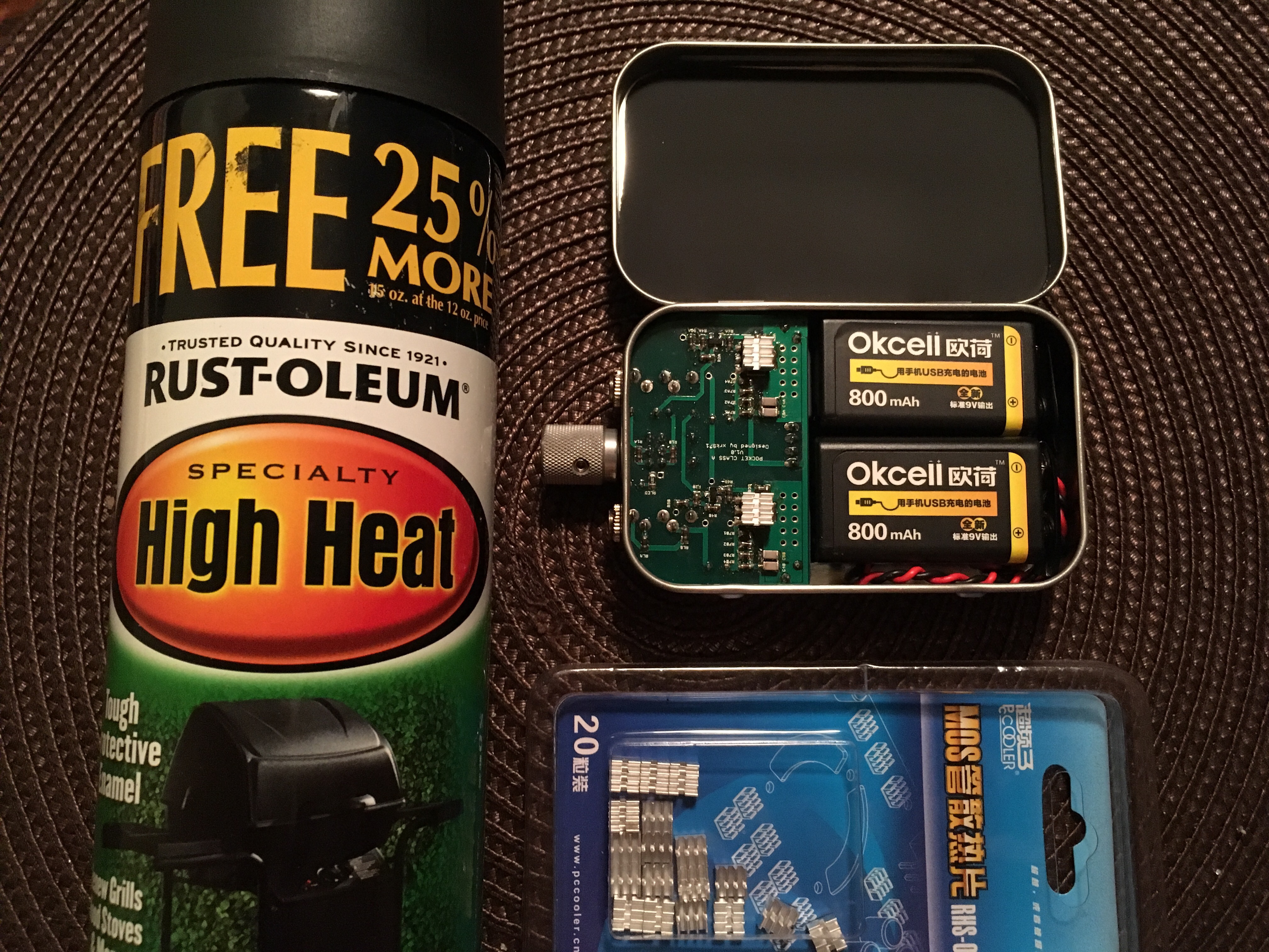
Charging the batteries inside the tin is a partial success.  I made some big (not so pretty but oh so functional) cutouts in the tin using a hole punch to start, followed by wire cutters and pliers, so that my cables could connect there, and hot glued my batteries in place in the tin.  Unfortunately the batteries must sit about 1/4" away from the wall due to the curve of the tin corner, so the holes had to be big enough for not just the actual micro USB connector had to fit inside, but the entire plastic head of the cable too, in order for the connectors to reach the batteries inside.

There are tiny holes in the end of the tin (smallest hole punch from my 3 piece set) to reveal the charge indicator lights of one cell.  From an angle it looks like the light doesn't line up with the hole, but it does.  It's just that the battery is set back a bit from the tin wall due to curving tin corners.

But the big letdown is that I can't use the Y cable I bought (double micro USB) to charge them both simultaneously from a single USB charger.  Well I did it at first actually...it just won't work while the batteries are connected to the amp.  I can charge the batteries in situ if I use two separate chargers with two separate cables.  I think this is because of a shared ground in the cable, which must complete a circuit between the two batteries when they are snapped into the amp's battery connectors.  This situation seems to always send one of the two batteries into some sort of limbo state.  Voltage drops instantaneously to 0.3V (which results in a high pitched noise coming through the headphones when the amp is powered back on.)  The battery comes out of limbo when charged alone with its own cable for a few seconds, and then behaves normally again.

X, I have a somewhat convoluted question for you, oh electronics guru.  Before I ever saw this weird charging behavior, I was listening to the amp and poking around in the amp with my multimeter, and I stuck the probes on both the negative pins of the battery connector on the board (don't ask me why, I'm an artist, not an engineer!).  Oops...Instantly music volume dropped drastically and I heard a high-pitched hum.  I thought I had fried my amp or something at first.  Then I measured the new batteries and found one had dropped to near zero voltage.  I charged it for a few seconds and it was fine again, back above 9V.  Now it works great except for in the charging-in-amp-with-Y-cable situation, when it returns to this same limbo state.  Did I cause ALL this limbo behavior by damaging the battery with my multimeter, or did I just trigger some sort of protection circuitry with my probes, which is now just recurring with my flawed charging setup?  The same finnicky battery makes an audible high-pitch whine when I measure it with my multimeter.  Not through the headphones!  Like something in the battery itself is oscillating while the voltage is read by the multimeter.  I'm not sure if it did this before my initial probe mishap or not, but only one of the batteries does this, so I wonder.  As I said, both batteries perform flawlessly in the amp, no noise. 

Sorry that was long...it was hard to explain.  My hope: If it is a protection circuit, Possibly the finnicky one is just slightly more sensitive so it always trips first, leaving the other one appearing not to have the behavior at all.
 
Mar 31, 2017 at 7:48 AM Post #178 of 468
You measured 15v at the output of the MOSFETs?! That's not possible unless amp is damaged as it means 127mA bias current. Way out of operational limits. Can you double check? The battery protect smart circuit kicked in when you shorted. Sometimes turn on in rush causes them to kick in and have to turn on off to charge rail caps.
 
Mar 31, 2017 at 11:52 AM Post #180 of 468
Hi StellarElelphant,
Can you check the bias current again with the new batteries?  Pin 2 might show what the two batteries are in series or about 16v to 18v.  Pin 3 should be somewhere in 5.5v to 7.5v.
Thanks,
X
 

Users who are viewing this thread

Back
Top