Need some schematic reading help
Mar 29, 2007 at 2:09 AM Thread Starter Post #1 of 6

pne

Headphoneus Supremus
Joined
Sep 13, 2004
Posts
2,571
Likes
14
littlegemMK2.png


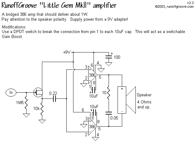
Just a really basic question, I'm trying to build this circuit and some of the cap values are not labelled. Am I to assume these are in microfarads? Also, the diagram shows a FET which I'm not entire sure how to hook up. Can anyone shine a light on this? Lastly this is my first attempt at a bridged amp, it looks like the input is going into pin 2 of the first opamp and pin 3 of the second. Is this correct?
 
Mar 29, 2007 at 2:39 AM Post #2 of 6
Yes that is how bridged operations work. Inverting one signal, and non-inverting the other. The cap values are microfarad. The FET is hooked up as is shown. The input goes to the gate, the drain to 9v, and the source to the junction 10k/0.22uf
 
Mar 29, 2007 at 2:51 AM Post #4 of 6
Quote:

Originally Posted by Garbz /img/forum/go_quote.gif
Yes that is how bridged operations work. Inverting one signal, and non-inverting the other. The cap values are microfarad. The FET is hooked up as is shown. The input goes to the gate, the drain to 9v, and the source to the junction 10k/0.22uf


thank you very much!!
 
Mar 29, 2007 at 4:08 AM Post #5 of 6
The LM386 was designed as a low cost transistor radio amplifier chip with very minimal external parts count, as such it is not very "hi-fi". Running it balanced allows more output power, but the schematic posted above states "4 ohm or greater" speaker load. In balanced operation, each amp "sees" half the load impedance, therefore for a 4 ohm speaker, the load would appear to be 2 ohms. That is an awfully low impedance for the little DIP8 chip and I question the validity of using the chip that way. Of course, as a headphone amp the load would be much lighter and this would not be an issue, but I wouldn't get my hopes up too high about its actual performance, balanced or unbalanced.
 
Mar 29, 2007 at 5:48 AM Post #6 of 6
Quote:

Originally Posted by amb /img/forum/go_quote.gif
The LM386 was designed as a low cost transistor radio amplifier chip with very minimal external parts count, as such it is not very "hi-fi". Running it balanced allows more output power, but the schematic posted above states "4 ohm or greater" speaker load. In balanced operation, each amp "sees" half the load impedance, therefore for a 4 ohm speaker, the load would appear to be 2 ohms. That is an awfully low impedance for the little DIP8 chip and I question the validity of using the chip that way. Of course, as a headphone amp the load would be much lighter and this would not be an issue, but I wouldn't get my hopes up too high about its actual performance, balanced or unbalanced.


thanks for letting me know. The circuit is designed as a portable guitar amplifier, I guess we'll have to see how it sounds. You're right about one thing, it is cheap!
 

Users who are viewing this thread

Back
Top