need idea for 12v motor control (alps)
Oct 30, 2008 at 8:29 PM Thread Starter Post #1 of 17

linuxworks

Member of the Trade: Sercona Audio
Joined
Oct 10, 2008
Posts
3,456
Likes
68
I have some more motorized pots coming on order and I thought I'd ask what people are using to control them.

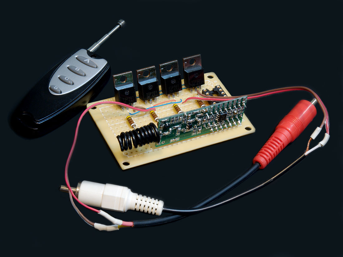
my first version uses 'simple and dumb' relays. these are dc motors and you either run 12v in one polarity to get one rotation and reverse the leads to get the motor to spin the other way. its super simple but I'd like to remove the relay and do it all silently (transistors maybe).

currently, I use 2 DPDT relays and you activate one relay to get one spin direction or the other for the other. all the relays do is map the 2 poles +/- to NC pins that are straight or swapped (from relay 1 or 2). its that simple and it works fine. but there's this annoying click everytime I remotely control these and I want to get rid of that
wink.gif


also, my control inputs are going to be pushbutton modeled as you'd expect: press and hold to move the motor and release the button (the up or down button) to stop the motion. no latching in this circuit, just momentary presses mapped to pos or neg polarity volts to the motor.

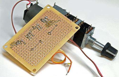
btw, here's an early view of my first version:

2948885036_bc3d542561.jpg


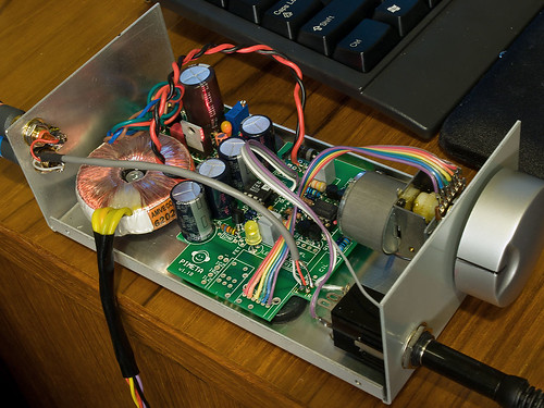
this was before I had the relays or the IR receiver connected. the motor pot is there just begging to be connected
wink.gif


anyone have an already-worked-out solution that doesn't use relays for motor reversing?
 
Oct 31, 2008 at 12:50 AM Post #2 of 17
motor_driver.jpg


This will do what you want... however there's some implementation issues with turning the upper mosfets on. Typically when this configuration is used in a power supply, a thing called a "bootstrapped" gate driver is used to turn the upper mosfets on and off.

That won't really work here since you're not switching them very fast. However, since you're not turning them on very often, you could get away with just applying 12V to the gate, and letting them sit with the gate-source voltage equal to drain-source voltage, which normally causes a lot of power loss in the transistors, but doesn't matter much for this application (moderate peak power dissipation, but reaaaally low average power dissipation).
 
Oct 31, 2008 at 1:53 AM Post #3 of 17
thanks!

that might give me some ideas. although I'm a bit weak on non-bipolar transistor theory.

I found this in a search:

DC Motor Control Circuit

motor.gif


it seems similar but uses BPT
wink.gif


so that topology is what seems to be 'the thing'.

I wonder if there are prebuilt modules for this? ok, so I'm slightly lazy right now
wink.gif
 
Oct 31, 2008 at 9:39 PM Post #7 of 17
If you want to be lazy, you can buy a cheap motor controller kit that was designed for the RepRap DIY 3D prototyping gizmo. This design uses the L293D chip from TI which incorporates two 'H' bridges (the transistor circuit you're looking at) on a DIP-16 IC. It includes two motor controllers on a small board. Instead of PWM signals, just attach the outputs from your IR decoder.

You can find similar kits/pcbs on many DIY robotics sites, as it's a ubiquitous circuit in that field.
 
Oct 31, 2008 at 10:03 PM Post #8 of 17
so many good ideas and great help, here!

thanks everyone.

I ordered one of those reprap kits. I always like seeing how small kit makers put their stuff together for sale and I do like supporting kitmakers with my $$.

h-bridge. I learned some new stuff today. I love it.

I'll update as I find good ways to integrate this with my amp. it sure beats the relays I was using in my last build
wink.gif
 
Oct 31, 2008 at 10:15 PM Post #9 of 17
Don't forget you'll need a way to derive the direction signal, probably with an inverter on the 'go lower' signal or something similar. You could also get tricksy and use one motor controller for each direction with the DIR input tied to opposite rails and the outputs paralleled. It's a bit wasteful of what capabilities you have, but you don't need any additional components to do it. Just make sure that the two switches can't both be on simultaneously or you'll fry the L293D.
 
Oct 31, 2008 at 10:21 PM Post #10 of 17
on my last build, I used a 7474 (or cmos version) to latch one of the TTL signals from my IR decoder circuit. I used a press on/press off model to turn on/off my crossfeed. that was one latch and 1 relay.

for volume control, I allocated 2 buttons on my remote (so that's 3 total so far) and this was not a toggle, it was momentary as you'd naturally expect.

the TTL output from my IR module is debounced, it seems, and so I have a logical 1 on the 'vol up' wire or a logical 1 on the 'vol down' wire and hopefully I don't have to police them both being 1 at the same time
wink.gif


so other than something that takes TTL1 on 1 of 2 lines (exclusively) I should be all set.

now, if I wanted varying speeds, THAT would be a bit more involved. 2 more buttons to 'scoot along faster' maybe?
wink.gif
probably overkill. probably the whole motor thing is overkill (lol) but its fun.
 
Nov 21, 2008 at 5:16 AM Post #11 of 17
update:

I built the rep-rap kit and it works fine.

I also built my own from discrete parts and it was really trivial.

3047582198_8649ae64fa_o.jpg


3046746703_fbc498aa25.jpg


I did a quick circuit layout (actually, my first ever eagle project) and this is 1-layer-able. it may not be optimum but it was very easy to wire.

the red/brown is +5 and ground. the curled up yellow,orange wires are the control lines. touch a control line to +5 and the pot spins one way. touch the other line to +5 and it spins the other way.

all transistors are tip101 and they have built in 10k R's in the right places and diodes in the right places, too
wink.gif
so all that was needed was a single R on each base ("all your base R belong..." ah, nevermind)
wink.gif


what I now need is to interface this to low-triggered ttl (which is what both my rf remote and ir remote receiver uses). I'll slap in a 7400 and put those gates into invert mode and convert the ground-going triggers to plus-going triggers.

the receivers both ensure that only 1 line can go low at a time so I don't need ANY extra 'mutex' stuff to protect the circuit.

my version of the schematic:

3046775247_e117a868c9.jpg


my first cut of the board:

3047610750_20d624fdd2.jpg


I took some time to try to teach myself eagle. this was my first project! fwiw
wink.gif


update: new photos of the RF receiver module soldered in and WORKING!

3047764841_b80cec22b8_o.jpg


3047764997_f1e3609726_o.jpg
 
Nov 25, 2008 at 5:05 AM Post #12 of 17
here's an idea I have - please tell me if you think it would work:

3057380023_597802260b_o.gif


what I did was to take the standard h-bridge circuit and add 2 voltage busses. a common ground is used so the 'bottom' row of transistors is used for both high and low speed; but the top transistors are going to be the 'inside' ones for lower speed (from 5v) or the outer ones that take their top rails from 12v.

will this work?

I tried to use diodes as an OR, sort of, so that the logic levels that turn the transistors on and off won't leak back and turn the wrong alternate ones on.

there may even be ways to optimize this (?)

but will it work? I wanted to avoid PWM style motor speed controls and allow a fast-up, fast-down, slow-up and slow-down via 4 buttons.

comments?
 
Nov 25, 2008 at 10:27 AM Post #13 of 17
Q1 and Q3 should not be reverse biased in this fashion. This will probably exceed their maximum e-b voltage rating.

I think your control stuff is okay, though I'm unsure of why you have the extra diodes into the base. One diode to isolate the other control pin should be fine. You should also have power diodes to protect against EMF on the motor leads. And make sure your transistors have sufficient current gain. You probably want to use darlingtons or MOSFETs (though beware of Vth). Also, 5V at the top of this circuit may not work since the transistors will each drop Vce(sat) across their c-e junction. This is usually 0.5-1V. Using MOSFETs would help with this since they appear as a (low) resistance when on, instead of having a relatively constant voltage drop. Something like IRF540 is probably suitable, it has a fairly low Vth (4V max) and fairly low Rds(on) (0.05R). You absolutely must include the reverse bias protection diodes if you use MOSFETs.
 
Nov 25, 2008 at 2:12 PM Post #14 of 17
Quote:

Originally Posted by error401 /img/forum/go_quote.gif
Q1 and Q3 should not be reverse biased in this fashion. This will probably exceed their maximum e-b voltage rating.


the thing is, the first version I built DID work and it used the same topo for q1 and q3.

Quote:

I think your control stuff is okay, though I'm unsure of why you have the extra diodes into the base. One diode to isolate the other control pin should be fine.


which ones could I remove, then?

Quote:

You should also have power diodes to protect against EMF on the motor leads.


this was why I picked the TIP101 style transistors. they have back EMF diodes built in and also biasing R's for 10k in the usual places, so that level of integration is already done internally.

Quote:

And make sure your transistors have sufficient current gain. You probably want to use darlingtons or MOSFETs (though beware of Vth). Also, 5V at the top of this circuit may not work since the transistors will each drop Vce(sat) across their c-e junction. This is usually 0.5-1V. Using MOSFETs would help with this since they appear as a (low) resistance when on, instead of having a relatively constant voltage drop. Something like IRF540 is probably suitable, it has a fairly low Vth (4V max) and fairly low Rds(on) (0.05R). You absolutely must include the reverse bias protection diodes if you use MOSFETs.


I didn't think too much about the voltage drop but 5v wasn't so much literal but more as a 'lower than 12' level. maybe I'll pick 9v or something.

fwiw, in the old config (no q5 or q6) and only 5v going to the whole circuit, the pots move very slowly but they do move and the circuit does switch the directions as you'd expect.

I was trying to increment the design and add a 'high and low voltage' control set of transistors instead of playing the usual PWM games to vary speed.

and, thanks for the comments!
 
Nov 25, 2008 at 5:07 PM Post #15 of 17
The 'A' diodes could be removed. And yea, I wasn't sure if that's what you meant or if you already had 12V and 5V available.

You built this already? Why are you asking if it's going to work then
wink.gif
.

The problem is that if 12V appears at the emitters of Q1 and Q3 due to Q5 and Q6 being on, they will be reverse biased with 12V. I don't think you could come across this situation without having added Q5 and Q6. You should add diodes to the emitters of these transistors to protect them - but you'll lose another 0.7V as a result.
 

Users who are viewing this thread

Back
Top