Modeling headphone's acoustic performance
Sep 22, 2011 at 10:34 PM Thread Starter Post #1 of 17

arnaud

Stax and Sushi
Joined
Nov 26, 2002
Posts
2,994
Likes
1,492

 
Edit 9/24: new simulation results
 
For some obscure reason, every time a newborn surfaces at home, I somehow get into the mood to use the software from my work to model the acoustic performance of headphones 
blink.gif
. Apart from deprieving me from sleep, I have found that this activity helped me gain some understanding of why a given headphone design behaves in a certain way. In particular, I have been trying to identify the influence of the headphone enclosure (resonances, absorption, radiation to the outside) on its subjective and / or objective performance.
 
I did a quick search for that kind of stuff here on HF but didn't find much so I thought it'd be nice to have a thread to discuss assumptions and results... In particular, one of the main issues is guessing of the properties for the transducer so any advice / experience one might have with headphones testing or diy mod would be welcome to refine the models... I have been getting some nice data from member Purrin as well as Tyll Hertsens over at InnerFidelity.com, it really helps with getting some confidence in the models...
 

Since my wife and I don't make babies that often, I have really just made models for two headphones so far 
biggrin.gif
.  I worked on the Sennheiser's HD800 when my first one was born ( discussed here: http://www.head-fi.org/t/468461/hd800-imaging-and-treble-why-and-how-it-can-be-improved-upon and more recently here  http://www.head-fi.org/t/566929/headphone-csd-waterfall-plots/135#post_7750130 ).
 
With the second baby born last week, I ventured into the modeling of Stax's SR009, and I have some preliminary results to share here. For the people familiar with modeling of vibro-acoustics, the current model was using coupled structural and acoustic Finite Elements. The exterior domain is severely truncated but acoustic boundary conditions are applied to simulate radiation into free field.
 
As a reference, here is a measurement of the SR-009 acoustic performance performed on dummy head by Tyll at Inner Fidelity. DISCLAIMER: these graphs were generated by me with my own post-processing routines. Although I try to pay attention, mistakes in the code / misunderstandings in the raw data may have occurred, trust with caution :wink:... Note also that these results are equalized (correction for the dummy head influence), but not averaged for different earcup positions so interpret with care (go to InnerFidelity website for equalized / averaged and other results). 

 
What got me curious is the source of resonances around 2-4kHz, illustrated here through Cumulative Spectral Decay Results (see Marv's fantastic work here for more info on this type results: http://www.head-fi.org/t/566929/headphone-csd-waterfall-plots ):


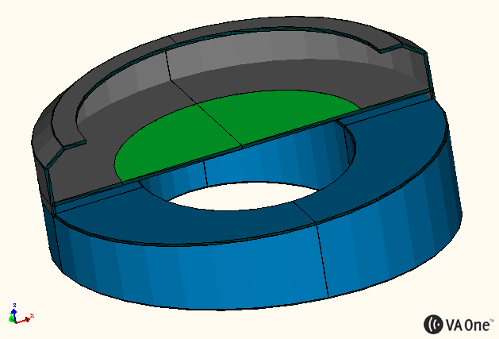
Now on to the SR009 (highly simplified) model. First the geometry, note that the earpads are currently modeled as rigid surfaces. Since there's a thick leather cover, it shouldn't that far off (little absorption):


Here is the resulting SPL at some locations ~1cm above the "ear surface" (currently assumed to be a rigid surface, I may be able to add actual dummy head geometry later on). The microphones at above 1cm apart so you can see typical variations as the headphone is moved around:


Then, some illustration of the pressure response around the headphone and vibration of the membrane at the 3.5kHz (acoustic resonance in the earcup cavity) and 6kHz (lobes in the SPL response at the mic locations):


Finally, an animation of coupled structural/acoustic dynamics at the same 2 frequencies.  Note that the diaphragm material is bogus as I have absolutely no idea of the tensioning and resulting natural frequencies. I just used a 1.5 micro meter nylon with increased stiffness to simulate the tension and adjusted that to get the first diaphragm "piston" mode at about 50Hz. This turns into over a thousand wiggling modes in the diaphragm by 10kHz... BTW, the diaphragm is modeled as a circular membrane with "pinned" boundary conditions, which should be fairly realistic. Also, note that these animations are NOT to scale, they just illustrate the vibration and pressure radiation pattern:


More later... Any advice, comments or questions welcome!
 
Cheers, arnaud
 
 
Sep 22, 2011 at 11:43 PM Post #2 of 17
You measure them as if base surface is rigid and non-absorptive.... which is not true at all in real situation. 
o2smile.gif

 
Since it is rather silly to waste $10000+ on dummy head... I suggest use alternative material like very hard sponge wrapped by smooth cloth.
 
Sep 22, 2011 at 11:54 PM Post #3 of 17
as one who invested 7 big ones on a pair of SR009 and a Stax amp, can you please sum up what all this techno means?
Should I have saved 2 big ones instead with the SR007?


Quote:
 
For some obscure reason, every time a newborn surfaces at home, I somehow get into the mood to use the software from my work to model the acoustic performance of headphones 
blink.gif
. Apart from deprieving me from sleep, I have found that this activity helped me gain some understanding of why a given headphone design behaves in a certain way. In particular, I have been trying to identify the influence of the headphone enclosure (resonances, absorption, radiation to the outside) on its subjective and / or objective performance.
 
I did a quick search for that kind of stuff here on HF but didn't find much so I thought it'd be nice to have a thread to discuss assumptions and results... In particular, one of the main issues is guessing of the properties for the transducer so any advice / experience one might have with headphones testing or diy mod would be welcome to refine the models... I have been getting some nice data from member Purrin as well as Tyll Hertsens over at InnerFidelity.com, it really helps with getting some confidence in the models...
 

Since my wife and I don't make babies that often, I have really just made models for two headphones so far 
biggrin.gif
.  I worked on the Sennheiser's HD800 when my first one was born ( discussed here: http://www.head-fi.org/t/468461/hd800-imaging-and-treble-why-and-how-it-can-be-improved-upon and more recently here  http://www.head-fi.org/t/566929/headphone-csd-waterfall-plots/135#post_7750130 ).
 
With the second baby born last week, I ventured into the modeling of Stax's SR009, and I have some preliminary results to share here. For the people familiar with modeling of vibro-acoustics, the current model was using coupled structural and acoustic Finite Elements. The exterior domain is severely truncated but acoustic boundary conditions are applied to simulate radiation into free field.
 
As a reference, here is a measurement of the SR-009 acoustic performance performed on dummy head by Tyll at Inner Fidelity. DISCLAIMER: these graphs were generated by me with my own post-processing routines. Although I try to pay attention, mistakes in the code / misunderstandings in the raw data may have occurred, trust with caution :wink:... Note also that these results are not equalized (correction for the dummy head influence), and not averaged for different earcup positions so interpret with care (go to InnerFidelity website for equalized / averaged and other results). 

 
What got me curious is the source of resonances around 2-4kHz, illustrated here through Cumulative Spectral Decay Results (see Marv's fantastic work here for more info on this type results: http://www.head-fi.org/t/566929/headphone-csd-waterfall-plots ):


Now on to the SR009 (highly simplified) model. First the geometry, note that the earpads are currently modeled as rigid surfaces. Since there's a thick leather cover, it shouldn't that far off (little absorption):


Here is the resulting SPL at some locations (see blue color sensors in contour plot later down this post) at the base of the earcup. Note that the dummy head is not currently modeled, and I am simply assuming the base surface where the pad lies is perfectly rigid and non-absorptive (not a very good model, I may be able to add actual dummy head geometry later on). Maybe it's far fetched but the simulation shows the resonances at around 3.5kHz and 6.5Khz, similar to Tyll's test:


Then, some illustration of the pressure response around the headphone and vibration of the membrane at the two main predicted resonances (3.7kHz and 6.6kHz):
 
SR009_FEM_ContourPlot_3700Hz.jpg

 
SR009_FEM_ContourPlot_6600Hz.jpg


Finally, an animation of coupled structural/acoustic dynamics at the 3.7kHz. Note that the diaphragm material is bogus as I have absolutely no idea of the tensioning and resulting natural frequencies. I just used a 1.5 micro meter nylon with increased stiffness to simulate the tension and adjusted that to get the first diaphragm "piston" mode at about 50Hz. This turns into over a thousand wiggling modes in the diaphragm by 10kHz... BTW, the diaphragm is modeled as a circular membrane with "pinned" boundary conditions, which should be fairly realistic. Also, note that these animations are NOT to scale, they just illustrate the vibration and pressure radiation pattern:


More later... Any advice, comments or questions welcome!
 
Cheers, arnaud


Sep 23, 2011 at 12:32 AM Post #4 of 17


Quote:
as one who invested 7 big ones on a pair of SR009 and a Stax amp, can you please sum up what all this techno means?
Should I have saved 2 big ones instead with the SR007?


What he done here is merely showing us data for STAX headphones.... He does not suggest that you should also get SR007.
 
However, Tyll's measurements (http://www.innerfidelity.com/content/beginning-electrostatic-headphone-measurements) shows that SR007 have quite several technical edges over SR009.
 
 
Say, LCD-2's measurement is by far best I've ever seen. Look at 30 Hz square wave; considering LCD-2 is regarded as 'warm' headphones, it is just incredible. But, it does not mean that STAX SR009 headphones are bad or terrible, either (opposite is true. Such amazing headphones and among with SR007, it is only STAX that is worth for listening IMO.)
 
Quite many headphones have really terrible measurement yet have really high price-tag. Pretty much all Grados, including the most expensive PS1000, have really terrible graphs (wow I am surprised! 
rolleyes.gif
 ). And Ultrasone Edition 10, which is actually far more expensive than SR007+amp combo, has such unbelievably bad measurements.


Plus:
 
 
And almost most of time, those measurements indeed tell you the sound quality of the headphones as well.


Example: I CANNOT listen to ANY stock Grado headphones for more than 15 sec. Their strong coloration and extremely aggressive treble make my ears bleed in such short time. My very first Grado were SR225 from a local dealer, and I really strongly believed that those were defective cans. After hearing other models, I realized that they were not defective.
 
If it weren't my friend's SR60 with TTVJ Flat pads, I wouldn't bother into Grado headphones, if at all. With Flat pads, they completely change into different headphones (read: enjoyable.)
 
This is the data for SR225i with stock pads.
http://www.innerfidelity.com/images/GradoSR225i.pdf
 
And this is for ones with Flat pads
http://www.innerfidelity.com/images/GradoSR225iTTVJFlatPads.pdf
 
 
As you see, the whole frequency graph gets more balanced, and crucial 300 Hz square wave becomes more 'square' than stock pad. Heck, Those flat pads even make the headphones faster (see improved impulse response) as well.

 
Sep 23, 2011 at 12:56 AM Post #5 of 17


Quote:
You measure them as if base surface is rigid and non-absorptive.... which is not true at all in real situation. 
o2smile.gif

 
Since it is rather silly to waste $10000+ on dummy head... I suggest use alternative material like very hard sponge wrapped by smooth cloth.


Actually, my stuff is simulation only. For the measurements, Tyll is using an actual dummy and Marv is doing both rigid and absorptive back plate. I guess your recommendation is to simulate the acoustic impedance of human skin? I can try any type of material layup and apply to the base panel so any such recommendation is welcome. First thing though, I want to see the effect of the pinna on the simulation as the test data I have currently includes that physics. Purrin is getting his pair of 009 any day now though so hopefully I can get my hands on rigid/anechoic plate data shortly (Marv, will you? :wink: )
 
 
Quote:
as one who invested 7 big ones on a pair of SR009 and a Stax amp, can you please sum up what all this techno means?
Should I have saved 2 big ones instead with the SR007?


Not at all, as a matter of fact, listening to the 009 while building this model was distractive because this headphone is so immersive :wink:. I myself do not have an easy time to interpret the test or simulation results so at the moment, this is merely an exercise of understanding the physics of headphone sound reproduction... Having said that, well you can tell from the FRF comparison that the 007 and 009 sound nowhere near the same and this clearly correlates with subjective impressions. As for which one sounds better, I think pretty much 90% of the impressions posted to date on this and other sites (and soon on Inner Fidelity website - Tyll is reviewing both high end Stax phones) converge toward the same impressions so you probably already got the picture.
 
Quote:
What he done here is merely showing us data for STAX headphones.... He does not suggest that you should also get SR007.


Yes indeed, thank you for clarifying :wink:. I am with you on the late Grado's performance, I was about to use that to reply to Pauchiu but you did the job just fine :wink:.
 
 
Sep 23, 2011 at 1:56 AM Post #6 of 17
Thanks for that wnmnkh,
 
I am a closet ED10 user, kinda love it for monitoring my son's piano pieces.  strange that the sinusoidal varies wildly but in use mimics his Steinway nearly perfectly....
 
I guess i will wait for Monday when my Stax finally arrives.
 
Paul


Quote:
 
What he done here is merely showing us data for STAX headphones.... He does not suggest that you should also get SR007.
...............
Quite many headphones have really terrible measurement yet have really high price-tag. Pretty much all Grados, including the most expensive PS1000, have really terrible graphs (wow I am surprised! 
rolleyes.gif
 ). And Ultrasone Edition 10, which is actually far more expensive than SR007+amp combo, has such unbelievably bad measurements.
 
....


Sep 23, 2011 at 1:59 AM Post #7 of 17
Thanks!
 
..just finished another hour of LCD-2 head clamping....  (remember Adam's Family?)
 
nite
 
Paul


Quote:
Actually, my stuff is simulation only. For the measurements, Tyll is using an actual dummy and Marv is doing both rigid and absorptive back plate. I guess your recommendation is to simulate the acoustic impedance of human skin? I can try any type of material layup and apply to the base panel so any such recommendation is welcome. First thing though, I want to see the effect of the pinna on the simulation as the test data I have currently includes that physics. Purrin is getting his pair of 009 any day now though so hopefully I can get my hands on rigid/anechoic plate data shortly (Marv, will you? :wink: )


Not at all, as a matter of fact, listening to the 009 while building this model was distractive because this headphone is so immersive :wink:. I myself do not have an easy time to interpret the test or simulation results so at the moment, this is merely an exercise of understanding the physics of headphone sound reproduction... Having said that, well you can tell from the FRF comparison that the 007 and 009 sound nowhere near the same and this clearly correlates with subjective impressions. As for which one sounds better, I think pretty much 90% of the impressions posted to date on this and other sites (and soon on Inner Fidelity website - Tyll is reviewing both high end Stax phones) converge toward the same impressions so you probably already got the picture.
 

Yes indeed, thank you for clarifying :wink:. I am with you on the late Grado's performance, I was about to use that to reply to Pauchiu but you did the job just fine :wink:.


Sep 24, 2011 at 2:22 AM Post #8 of 17
Hi arnaud,
 
How far are you going to take this simulation?  For instance are you going to include:
 
  1. real values of compliance of mylar minus the negative compliance due to biasing, correct density,  etc.? - if so I will try to the find out the correct values.
 
  1. the acoustic impedance of the trapped air between the stators, this are is quite extensive in the outer ring of the 007/009 etc - complex, the stator being so thin and itself partially acoustically transparent,  with resonant modes - another edge clamped membrane!
 
  1. the dust covers, are they significant
 
  1. the acoustic impedance of the holes in the stator
 
  1. any additional damping material, sorry I am not familiar enough with all the variations of the circular diaphragm Stax headphones to know what damping material is used, if any.  In any case changing damping material would be interesting. The modes you illustrate will require airflow transversely across the diaphragm, this flow being transverse and very close to the diaphragm, should be affected by a relatively thin damping layer.  Moving the damping layer along the Z axis (normal to the membrane) would be quite revealing.
 
  1. electrical interaction: From the modeling viewpoint, it is lucky that there is very little interaction between the amp and the phones, also the electrical circuit is very simple with no resistances to electrically damp the diaphragm. Indeed almost all power goes to radiated audio power, with only a little lost to acoustic damping - making the ES the most efficient speaker watt for watt around.
 
  1. any other case related materials such as covers, protective grids, .  Although a bit of an extreme example, the covers on Quad ESL57s altered the frequency response quite a bit.  I haven't seen a CSD of the change to see whether resonances were also altered.
 
 
No pressure, just curious.
Regards,
Bob
 
 
Sep 24, 2011 at 6:50 AM Post #9 of 17
Hi Bob,
Welcome to Head-Fi!
 
I surely plan on doing a few sensitivity studies and your inputs below are very good ideas. Only limitation is how much can be done by simulation but i have a few ideas :wink:.
 
arnaud
 
PS: all simulation results were updated in the first post... A few more mics / more spaced apart to highlight sensitivity of the response as frequency increases (see 6kHz variations) and cleaner animations.


Quote:
Hi arnaud,
 
How far are you going to take this simulation?  For instance are you going to include:
 
  1. real values of compliance of mylar minus the negative compliance due to biasing, correct density,  etc.? - if so I will try to the find out the correct values.
 
  1. the acoustic impedance of the trapped air between the stators, this are is quite extensive in the outer ring of the 007/009 etc - complex, the stator being so thin and itself partially acoustically transparent,  with resonant modes - another edge clamped membrane!
 
  1. the dust covers, are they significant
 
  1. the acoustic impedance of the holes in the stator
 
  1. any additional damping material, sorry I am not familiar enough with all the variations of the circular diaphragm Stax headphones to know what damping material is used, if any.  In any case changing damping material would be interesting. The modes you illustrate will require airflow transversely across the diaphragm, this flow being transverse and very close to the diaphragm, should be affected by a relatively thin damping layer.  Moving the damping layer along the Z axis (normal to the membrane) would be quite revealing.
 
  1. electrical interaction: From the modeling viewpoint, it is lucky that there is very little interaction between the amp and the phones, also the electrical circuit is very simple with no resistances to electrically damp the diaphragm. Indeed almost all power goes to radiated audio power, with only a little lost to acoustic damping - making the ES the most efficient speaker watt for watt around.
 
  1. any other case related materials such as covers, protective grids, .  Although a bit of an extreme example, the covers on Quad ESL57s altered the frequency response quite a bit.  I haven't seen a CSD of the change to see whether resonances were also altered.
 
 
No pressure, just curious.
Regards,
Bob


Sep 24, 2011 at 7:17 AM Post #10 of 17
Oh, I forgot to mention: YES, absolutely interested if you can get me some properties for the Mylar. Well, only thing though is that I need to know the compliance UNDER tension (so maybe pulling it out from the resonances in an electrical impedance test in free field as you mentioned on the other site...). Maybe this is something that Marv (member Purrin) could pull off.
 
On the simulation side, unfortunately, although I know how to calculate pre-stressed structural modes in cased of a curved structure, I just haven't been able to get anything reasonable when the tension is in-plane for a flat membrane.... Actually, I can get access to other codes that could do it (like an explicit solver for linear or non-linear structural dynamics calculations) but I would still need to know the tension force (and Mylar properties / thickness obviously) and nobody knows that except Stax at the moment...
 
arnaud
 
Quote:
Hi arnaud,
 
How far are you going to take this simulation?  For instance are you going to include:
 
  1. real values of compliance of mylar minus the negative compliance due to biasing, correct density,  etc.? - if so I will try to the find out the correct values.
 
  1. the acoustic impedance of the trapped air between the stators, this are is quite extensive in the outer ring of the 007/009 etc - complex, the stator being so thin and itself partially acoustically transparent,  with resonant modes - another edge clamped membrane!
 
  1. the dust covers, are they significant
 
  1. the acoustic impedance of the holes in the stator
 
  1. any additional damping material, sorry I am not familiar enough with all the variations of the circular diaphragm Stax headphones to know what damping material is used, if any.  In any case changing damping material would be interesting. The modes you illustrate will require airflow transversely across the diaphragm, this flow being transverse and very close to the diaphragm, should be affected by a relatively thin damping layer.  Moving the damping layer along the Z axis (normal to the membrane) would be quite revealing.
 
  1. electrical interaction: From the modeling viewpoint, it is lucky that there is very little interaction between the amp and the phones, also the electrical circuit is very simple with no resistances to electrically damp the diaphragm. Indeed almost all power goes to radiated audio power, with only a little lost to acoustic damping - making the ES the most efficient speaker watt for watt around.
 
  1. any other case related materials such as covers, protective grids, .  Although a bit of an extreme example, the covers on Quad ESL57s altered the frequency response quite a bit.  I haven't seen a CSD of the change to see whether resonances were also altered.
 
 
No pressure, just curious.
Regards,
Bob


Sep 25, 2011 at 7:41 AM Post #11 of 17
Hi Arnaud,
 
Hmm, There is a way to determining the compliance of the membrane.  The primary resonant mode is determined by the mass and total compliance of the system when energised.  The total compliance is the sum of the mechanical compliance (under tension) and the negative compliance generated by the bias voltage.  If you vary the bias voltage the primary resonant frequency will change.  As long as you have a reasonably accurate physical model of the headphones you can work out the negative compliance and thus from the change of resonate frequency you can calculate the mechanical compliance of the diaphragm. 
 
An alternative, assuming that the stators are well insulated and cannot arc over to the diaphragm, is to build a small rig that earths the stators and applies an increasing bias until the electrically generated compliance equals the mechanical compliance at which point the diaphragm will collapses against the stator.   Baxandall has the method for calculating the values.  Usually you can hear the diaphragm slap (at least in my homemade ES phones) but an alternative is to connect the stators through a small resistor and connect your amp/testgear to point between the resistor and stator, when it collapses you will get a signal as the phones will be acting as a microphone.
 
I an not sure I follow, are you saying that you do not have a reasonable model for where the restoring force is within the plane of the membrane, that is, the diaphragm as used in the ES phones?
 
The thickness of the diaphragms and some other physical data seems to be known by Spritzer but is he telling ALL that he knows?  The density of the mylar is probably fairly easy to find, It is probably much the same as any other mylar film (any coating or treatment for conductivity probably will not alter it much).  I know that the Hostaphan RE range has a density of  1.395 g/cubic centimeter (approx1.9 grams per square metre for the 1.35micron thickness diaphragm). The membrane mass will have little effect until quite high frequencies so even an error of 50% is probably not much for the simulation (have you tried to increase the membrane mass by an order of magnitude to see what happens? - a good check on the model). The Young's modulus is 4500 Newtons per mm squared in the direction of extrusion and 5000 Newtons per mm squared transverse to the direction of extrusion.
 
Regards,
Bob
 
Some things worth knowing are the stator material (circuit board - but what material?), the stator thickness, the stator hole size and spacing, stator diameter, diameter of the perforated area, and diaphragm diameter. I believe that the conductors are on the outside of the stator so the dielectric value would be good.  Spritzer puts the stator spacing at .5mm but is this just the air gap or is it the distance from the diaphragm to the stator conductor.  Yep, pretty much an exact physical specification of the cell,this info must be out there somewhere.
Quote:
Oh, I forgot to mention: YES, absolutely interested if you can get me some properties for the Mylar. Well, only thing though is that I need to know the compliance UNDER tension (so maybe pulling it out from the resonances in an electrical impedance test in free field as you mentioned on the other site...). Maybe this is something that Marv (member Purrin) could pull off.
 
On the simulation side, unfortunately, although I know how to calculate pre-stressed structural modes in cased of a curved structure, I just haven't been able to get anything reasonable when the tension is in-plane for a flat membrane.... Actually, I can get access to other codes that could do it (like an explicit solver for linear or non-linear structural dynamics calculations) but I would still need to know the tension force (and Mylar properties / thickness obviously) and nobody knows that except Stax at the moment...
 
arnaud


Sep 25, 2011 at 10:00 AM Post #12 of 17
Hi Bob,
 
Ok, the impedance test you're mentioning reminds me of my days at an audio manufacturer when I was measuring the compliance of a driver using various electrical impedance measurements, I have totally forgotten about this 
confused_face.gif
. Anyhow, I probably would not be the one to provide my SR009 for some collapsing / arcing test :wink:.
 
I think the tensioning must not be that different from previous generations, so someone's got to know some rough values or have some impedance data (need to ping spritzer or chinsettawong ...). Like for an electrodynamic driver, does the electrical impedance peak at the resonances? Well it's the piston mode for a regular driver so compliance is very high compared to the first mode of membrane but you say that for estat speakers you could see it on the impedance curve?
 
In regards to the membrane mass, I haven't done it but can tell you right now: the resonance frequencies of the diaphragm will shift down with increase mass, and not by a little ( ~ sqrt(K/M) ).
 
For the stator material, it is 3 layers of metal joint under high pressure / temperature. I am not familiar with manufacturing processes, but I believe spritzer referred to it as cold welding process. Since he will be dismantling his unit at some point, the stator thickness and mesh size should become known (only use I could make of it though is to compute the acoustic impedance of this perforated grill and possibly some equivalent damping for the thin air gap). 
 
Sep 25, 2011 at 12:35 PM Post #13 of 17
Hi arnaud,
 
Only electrostatics have the shift in resonance. 
 
No way to alter the compliance of a magnetic driver via external means.  Of course,you could attach mass to the cone.  I had some JBL 2231 15 inch drivers (similar to the more common 2235 model [interchangeable cones]).  These were low Q low Fr drivers, there was a whopping great 'resonance control ring' just under the dustcap which is how JBL got the characteristics. It wasn't very successful, the mass was just too great, the spiders had a tendency to fail such that the driver's at_rest_position was several mm forward of where it should have been, happened to six drivers so it wasn't an isolated case.  Two of these drivers came to a very sticky end.
confused_face_2.gif
Anyhow back to the electrostatics.
 
The method of just reducing the bias and noting the change in resonant frequency would work without endangering the drivers.  As to detecting the primary resonance, that should definitely be detectable.  In free air, the drivers should exhibit the classic 6db/octave rise in output with frequency but with a definite peak at the resonant frequency (quite strong). It will be reflected in the impedance (reciprocity) but that will take monitoring of the HV output rails to see (perhaps a transformer).
 
The mass of the moving system is made up of membrane mass and air mass (acoustic reactance).  At low frequency the mass of the diaphragm is dwarfed (by several order of magnitude) by the mass of the air. The acoustic reactance (and thus equivalent air mass) falls with frequency making the membrane mass significant at higher frequencies and thus rolling off the upper end.  This is why the Quad ESL57s could have heavier gauge membranes in the bass units without affecting their performance (much).  If you took a Stax ESL and put it in a vacuum chamber, the primary resonance would probably be in kHz range.
 
 
I thought I saw in another thread here spritzer stating that Stax changed from the mesh stators to to PCB stators for the Omega 2s.
 
Anyhow,I shall have a little think about all this, something I really haven't done properly - recently. I am stating to feel that I am getting quite out of kilter and missing quite a few things.
 
Regards,
Bob


Sep 26, 2011 at 11:45 AM Post #14 of 17
Finally got around to create and solve a different type of model (using the Boundary Element Method which basically helps to model radiation into unbounded exterior fluid):
  1. Got somewhat similar results to previous FEM model:
  2.  
 
  1. The resonance at 3.5kHz is still there so this was not an artifact of the FEM bonded exterior domain:
  2. The large variations across mics are also observed at higher frequencies, example here at 5.7kHz:
  3. Last but not least, I am not too dissatisfied with the correlation against tests (Tyll's non-compensated headphone data over at InnerFidelity.com) given all the simplifications in the current model (rigid base panel, rigid cushions, no perforated stator model, no diaphragm compliance data and so on...):
 
Sep 26, 2011 at 1:24 PM Post #15 of 17
Hi arnaud,

That is looking quite promising, it will be interesting to see if the FR is more affected by the transducer or the earcup geometry and surfaces. Is it possible to do a CSD sweep on the simulation with the software?  One thing I always tried to do was get some performance data on a driver in the free field.  Did you do an analysis of the diaphragm alone in the free field?  We know from Streng what that performance should be - complete with the specifications of the test ES speaker, eg., diameter, compliance, diaphragm density, etc.

I now realise that I was getting the 007s mixed up with the 009.  The 009 is a little simpler as it does not have the large outer annular area with no perforations.  Also the stators are metal (no circuit board dialectic to worry about) and I assume coated with an insulating material (whoops again with the dialectic).  Has anyone had a really good look at them to determine some of the design specs, the % open area would be good as well as hole diameter, spacing, stator thickness, etc - damn, there I go again.

I have looked at your translation of the Stax engineer's interview and I am convinced that there is something not mentioned.  I am very suspicious about this high temperature fabrication process, I can see no justification for such a process, in both the high cost and low yield, just to create the shape of the stator, there are much more main stream and reliable processes for simple shaping. 

I have no proof but I conjecture that they may be bonding together different materials either as a metal composite or maybe even a metal sandwich.  If so, it would be possible to control the stator's resonant behaviour and sound transmission properties.  This is really your area of expertise, but some sintered metal composites can be both light and internally damped through particle friction.  If you bonded two very thin but stiff metal skins on either side of a sintered metal composite , you would indeed have a metal sandwich with high stiffness to mass ratio (greater acoustic transparency) and with internal damping to kill off spurious resonances.  Now, if true, wouldn't that be something! 

Anyhow, at the moment I am off to see if I can determine what type of model fits the perforated stator. Is it the simple resonator model in Beranek (referred to by Streng) or is it the more complex behaviour which is a combination of  "Squeeze-film Damping" and "Poiseuille flow"?  The latter model is generally used in microphones, I just don't know whether ES phones are within the range of the simpler model - I suspect not.  Unfortunately, the paper I want just isn't available on the internet, referred to many times but not downloadable.

See ya,
Bob
 

Users who are viewing this thread

Back
Top