Porksoda
500+ Head-Fier
- Joined
- Jan 7, 2004
- Posts
- 571
- Likes
- 0
Hello all,
I just picked up a Monica 2 kit, and have been considering a couple mods on it. I did some searching, and didn't find any threads on the subject, so I thought I would just throw it out here. See the following resource links:
TDA1545A Datasheet
Monica DAC (analog stage basically identical to Monica 2)

First off, I wanted to improve upon the power supply arrangement. I am not a fan of battery power, as I have seen some convincing arguements that a good regulated supply is better than batteries under dynamic loading. The convenience of wall power is a big plus aswell.
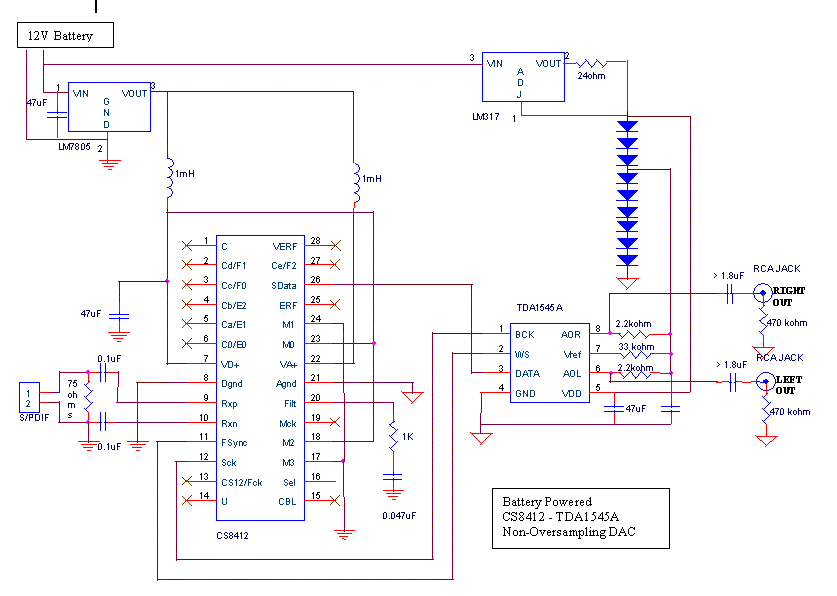
As it exists now, it uses a current source followed by a string of 4148 signal level diodes. VREF is then taken between two of the diodes such that it is approximately 2/3 of the total voltage. The more I think about it, this really isn't that bad a design. However, this design still has an LM317 in there without any real noise reduction, and the signal diodes form an entirely open-loop voltage supply. I was thinking more along the lines of dual independent Jung super regulators, especially considering the Vref is going to directly influence the noise and dynamic range of the output.
What are your thoughts on the advantages/drawbacks of this sort of power supply modding?
Second, I was thinking of adding some sort of active output stage to this thing. See this thread HERE for a circuit Glassman and I worked on based off of a design by Malcolm. It's a fully balanced, active, and non-inverting I/V stage. The only modification I would make is that GND would be instead connected to VREF, and of course you need to tack on an output buffer stage. Otherwise, you just connect the current output to Iin and you're good to go!
Again, what are your thoughts on this sort of modification and what sort of benefits or drawbacks it would have?
Thanks!
'soda
I just picked up a Monica 2 kit, and have been considering a couple mods on it. I did some searching, and didn't find any threads on the subject, so I thought I would just throw it out here. See the following resource links:
TDA1545A Datasheet
Monica DAC (analog stage basically identical to Monica 2)

First off, I wanted to improve upon the power supply arrangement. I am not a fan of battery power, as I have seen some convincing arguements that a good regulated supply is better than batteries under dynamic loading. The convenience of wall power is a big plus aswell.
As it exists now, it uses a current source followed by a string of 4148 signal level diodes. VREF is then taken between two of the diodes such that it is approximately 2/3 of the total voltage. The more I think about it, this really isn't that bad a design. However, this design still has an LM317 in there without any real noise reduction, and the signal diodes form an entirely open-loop voltage supply. I was thinking more along the lines of dual independent Jung super regulators, especially considering the Vref is going to directly influence the noise and dynamic range of the output.
What are your thoughts on the advantages/drawbacks of this sort of power supply modding?
Second, I was thinking of adding some sort of active output stage to this thing. See this thread HERE for a circuit Glassman and I worked on based off of a design by Malcolm. It's a fully balanced, active, and non-inverting I/V stage. The only modification I would make is that GND would be instead connected to VREF, and of course you need to tack on an output buffer stage. Otherwise, you just connect the current output to Iin and you're good to go!
Again, what are your thoughts on this sort of modification and what sort of benefits or drawbacks it would have?
Thanks!
'soda


