error401
1000+ Head-Fier
- Joined
- Oct 11, 2006
- Posts
- 1,244
- Likes
- 11
After receiving a request some time ago from theAnonymous1 over at that other board to write simple firmware to control a PGA2320 (or PGA2310), I found that I needed prototype hardware to test my code on. So I present to the community my board & schematic for critique. It seems like a simple volume control of this type is somewhat in demand around here, and hopefully my efforts will be useful to others.
The design is simple, just a small microcontroller and the PGA2320 chip, plus the necessary connectors (button headers, audio i/o, isp header and power). It is designed so that it can work with either up/down pushbuttons or a rotary encoder, with a configuration jumper to select. A mute button header is provided, with an indicator LED. EEPROM on the micro will allow the state to be saved between power cycles. The only other functionality provided is room for a 5V regulator so only +/- inputs are needed.
If you're not familiar with the PGA2320/PGA2310, they are TI's volume control parts (Burr-Brown division), based around digitally-controlled opamp gain stages. This allows a gain range from -95.5dB to 31.5dB (yes, you can add gain). For those applications that need it, a jumper is provided that will prevent the gain settings from being enabled (0dB cap).
On the specsheet, these chips are impressive, but there are some caveats when using them. This board addresses all of the datasheet notes on proper implementation but for one: no input buffer is provided. The IC should be driven by a source impedance of 600R or less, and analog performance will degrade if that's not satisfied, so if the source is the least bit weak, you'll need a buffer stage between the source and the volume control. I don't personally feel that an output buffer is necessary - PGA2320 can drive 600R loads quite well.
Firmware isn't done yet, but my prototype with a PGA2311, pushbuttons and no mute seems to work fine. It should not be difficult to extend the firmware to the planned state. When it's done and tested, the code will be released under an open source license (probably BSD).
Unfortunately, PGA2320 seems to be difficult to source right now, though TI does seem to be offering samples as usual.
BOM cost without the volume control is about $10.
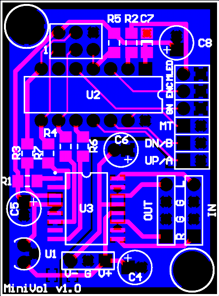
I have put in a fab order for 6 of the boards below. They should arrive in a couple weeks. I have 4 spares to let go to the first takers. Price is $10/board plus $1.50 shipping (US/Canada), just enough to recover my cost.
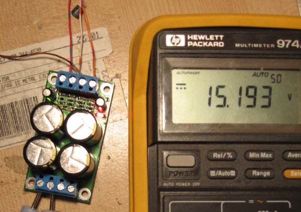
I have also designed a small (2.5" x 1.4"), all SMD +/-15V power supply based on LM317/337 and the various datasheet/internet recommendations for clean power. I ordered only one of these, but will give full documentation to anyone who asks for it. BOM cost for that is about $20.
Edit Jan 18, 2008: - I have put up a website for the project at MiniVol PGA2320 Volume Control - error404's Audio DIY Endeavours more details can be found there.
Board/Schematic PDF
Complete BOM
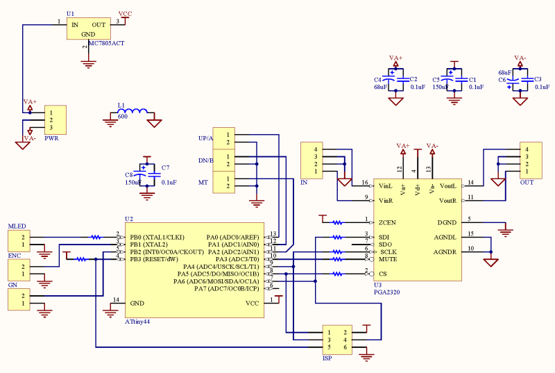
The design is simple, just a small microcontroller and the PGA2320 chip, plus the necessary connectors (button headers, audio i/o, isp header and power). It is designed so that it can work with either up/down pushbuttons or a rotary encoder, with a configuration jumper to select. A mute button header is provided, with an indicator LED. EEPROM on the micro will allow the state to be saved between power cycles. The only other functionality provided is room for a 5V regulator so only +/- inputs are needed.
If you're not familiar with the PGA2320/PGA2310, they are TI's volume control parts (Burr-Brown division), based around digitally-controlled opamp gain stages. This allows a gain range from -95.5dB to 31.5dB (yes, you can add gain). For those applications that need it, a jumper is provided that will prevent the gain settings from being enabled (0dB cap).
On the specsheet, these chips are impressive, but there are some caveats when using them. This board addresses all of the datasheet notes on proper implementation but for one: no input buffer is provided. The IC should be driven by a source impedance of 600R or less, and analog performance will degrade if that's not satisfied, so if the source is the least bit weak, you'll need a buffer stage between the source and the volume control. I don't personally feel that an output buffer is necessary - PGA2320 can drive 600R loads quite well.
Firmware isn't done yet, but my prototype with a PGA2311, pushbuttons and no mute seems to work fine. It should not be difficult to extend the firmware to the planned state. When it's done and tested, the code will be released under an open source license (probably BSD).
Unfortunately, PGA2320 seems to be difficult to source right now, though TI does seem to be offering samples as usual.
BOM cost without the volume control is about $10.
I have put in a fab order for 6 of the boards below. They should arrive in a couple weeks. I have 4 spares to let go to the first takers. Price is $10/board plus $1.50 shipping (US/Canada), just enough to recover my cost.
I have also designed a small (2.5" x 1.4"), all SMD +/-15V power supply based on LM317/337 and the various datasheet/internet recommendations for clean power. I ordered only one of these, but will give full documentation to anyone who asks for it. BOM cost for that is about $20.
Edit Jan 18, 2008: - I have put up a website for the project at MiniVol PGA2320 Volume Control - error404's Audio DIY Endeavours more details can be found there.
Board/Schematic PDF
Complete BOM

 .
.