


tomb
Member of the Trade: Beezar.com
- Joined
- Mar 1, 2006
- Posts
- 10,891
- Likes
- 1,066
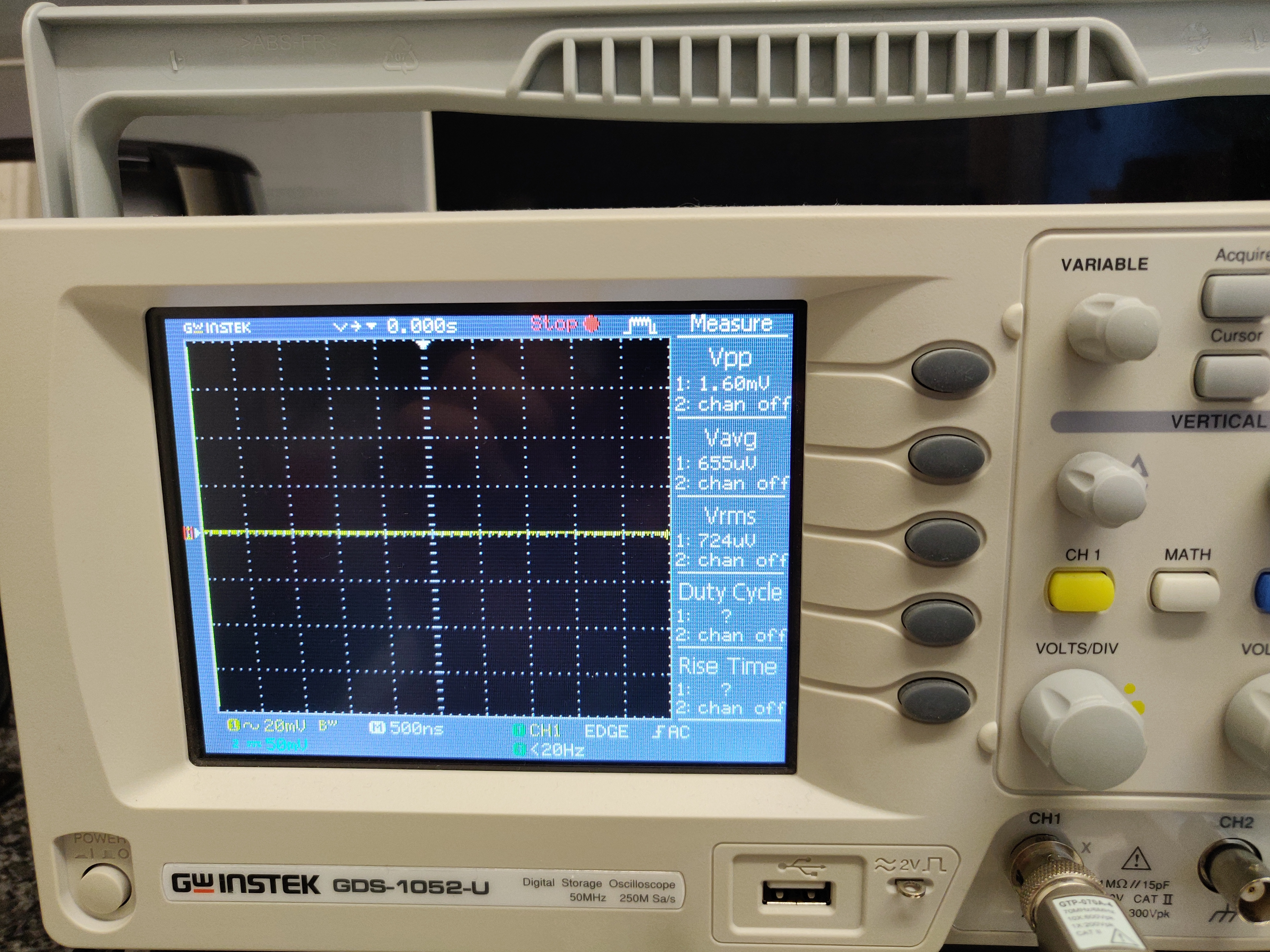
OK. With the help of a very good friend - Dsavitsk of ECP Audio - we've solved the oscillation issue with the volume pot. There is now no noise whatsoever in my volume pot travel. Gate stoppers on the MOSFETs fixed it. A Gate stopper consists of a 1K resistor inserted between the Gate leg of the MOSFET (center pin) and the center pin connection on the PCB. It takes some solder acrobatics, but most of you will probably have an easier time of it than I did, since I had already trimmed the MOSFET pins pretty short when I first built the NuHybrid. Here's some pics -
This is Q2 and Q3, with the 1K resistor inserted between the Gate leg of each MOSFET and the other lead of the resistor inserted into the Gate leg's pad on the PCB:

Basically, what you are looking at is one resistor lead is bent down vertically and inserted into the center hole on the PCB for the MOSFET. The other resistor lead is bent 180 degrees back over toward the MOSFET, whose Gate leg (center pin) is bent back up horizontally and soldered to the resistor lead on top of the resistor. As I said - yours probably won't look like this if you still have long leads on the MOSFETs. Note that I had to relocate the R19, R20, R22, and R23 resistors to the bottom of the PCB to make room for the Gate stopper resistors:

You can also see the 0.33uf Sonicap Gen IIs that I used for bypasses on the output caps.
Same Gate stopper applied to the MOSFET in the relay-delay:

This MOSFET is for the relay. It's not really in the signal path, but Dsavitsk suggested there might be some bleed-over if it oscillated, too. So, I put one here, too - just in case. The Gate stopper resistor had to twist over to the side because of C1. Be very careful if you do it this way that you don't short one of the outside legs of the MOSFET with the Gate leg and resistor lead.
Also note the C2 cap was upsized. This is a very inexpensive Murata 47uf 25V electrolytic. 25V is probably too low a rating, but I'm using a linear-regulated walwart at 24VDC anyway, so I doubt seriously it's going to be exposed to anything more than 24V. Still, the point is that you can find a bigger cap pretty easily (no high quality needed here) that should fit without any trouble. In my case, this extended the delay on power-up from about 6 seconds with the original cap to something over 30 seconds. Yeah, that's a hassle to wait that long, but when it kicks in now, there's only a very low "tap" that you can hear. Although, the "tap" sounds like a spoon tapping on a crystal glass.
 Before, the relay was engaging before my output caps had fully charged and was causing a nasty voltage spike and thump. There is still a turn-off thump, but I'm used to dealing with that a bit more than a turn-on one.
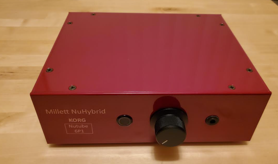
Here are a couple of overall pics -

and catching the glow from the NuTube -

Despite the camera setting, the NuTube glow is easily seen in daylight, unless you have some glare on the transparent NuTube cover. You can compare the green with the LED near the power switch. The NuTube glows with a very nice "ocean green" color just like some LEDs that I've sold as options on the Starving Student.
One other thing to note - the NuTube definitely has some microphonics, but it takes a real wallop to hear it. Unlike glass tubes with microphonics, the NuTube will "sing" at a very high-frequency pitch - like the crystal tap mentioned above. I will say that the only thing that causes this is being very rough and forceful when plugging in your headphones. There are a couple of reasons I was doing this - 1) I was plugging in after powering up, until I was certain that the turn-on thump was gone, and 2) with that little PCB setup on some metal standoffs, it takes some forceful action to hold it and plug the headphones in. If you are gentle and insert the jack slowly, you will not start the NuTube ringing. A good thing to mention is that nothing else I've done will cause it to ring - tapping it directly, shaking the PCB, or tapping anything else on the PCB. It only occured when violently shaking everything up plugging in the phones.
So how does it sound? I've been doing a lot of FM tuner work lately, so that's all I've heard it on thus far. However, I directly compared it to a pair of Mini3s and PIMETAs that I've been using in that work. The NuHybrid compares favorably to the Mini3, at least in this setup with a highly-modded Sony ES tuner. Detail is good, bass slam is great (note that I used 1000uf on the output caps) and it sounds very dynamic. The PIMETAs are smoother, but I think that may be a combination of the OPA627s in the PIMETAs, along with a very low gain. That's the last issue, I think - the NuHybrid has very high gain. I don't see any feedback loops except on the opamps and those are set to unity. Pete - if you have any suggestions on how to tame the gain, it will be greatly appreciated.
I'll report back when I get in some listening time on a quality DAC. Thank you Pete for this new toy and thanks to Dsavitsk for the oscillation solution!
This is Q2 and Q3, with the 1K resistor inserted between the Gate leg of each MOSFET and the other lead of the resistor inserted into the Gate leg's pad on the PCB:
Basically, what you are looking at is one resistor lead is bent down vertically and inserted into the center hole on the PCB for the MOSFET. The other resistor lead is bent 180 degrees back over toward the MOSFET, whose Gate leg (center pin) is bent back up horizontally and soldered to the resistor lead on top of the resistor. As I said - yours probably won't look like this if you still have long leads on the MOSFETs. Note that I had to relocate the R19, R20, R22, and R23 resistors to the bottom of the PCB to make room for the Gate stopper resistors:
You can also see the 0.33uf Sonicap Gen IIs that I used for bypasses on the output caps.
Same Gate stopper applied to the MOSFET in the relay-delay:
This MOSFET is for the relay. It's not really in the signal path, but Dsavitsk suggested there might be some bleed-over if it oscillated, too. So, I put one here, too - just in case. The Gate stopper resistor had to twist over to the side because of C1. Be very careful if you do it this way that you don't short one of the outside legs of the MOSFET with the Gate leg and resistor lead.
Also note the C2 cap was upsized. This is a very inexpensive Murata 47uf 25V electrolytic. 25V is probably too low a rating, but I'm using a linear-regulated walwart at 24VDC anyway, so I doubt seriously it's going to be exposed to anything more than 24V. Still, the point is that you can find a bigger cap pretty easily (no high quality needed here) that should fit without any trouble. In my case, this extended the delay on power-up from about 6 seconds with the original cap to something over 30 seconds. Yeah, that's a hassle to wait that long, but when it kicks in now, there's only a very low "tap" that you can hear. Although, the "tap" sounds like a spoon tapping on a crystal glass.
Here are a couple of overall pics -
and catching the glow from the NuTube -
Despite the camera setting, the NuTube glow is easily seen in daylight, unless you have some glare on the transparent NuTube cover. You can compare the green with the LED near the power switch. The NuTube glows with a very nice "ocean green" color just like some LEDs that I've sold as options on the Starving Student.
One other thing to note - the NuTube definitely has some microphonics, but it takes a real wallop to hear it. Unlike glass tubes with microphonics, the NuTube will "sing" at a very high-frequency pitch - like the crystal tap mentioned above. I will say that the only thing that causes this is being very rough and forceful when plugging in your headphones. There are a couple of reasons I was doing this - 1) I was plugging in after powering up, until I was certain that the turn-on thump was gone, and 2) with that little PCB setup on some metal standoffs, it takes some forceful action to hold it and plug the headphones in. If you are gentle and insert the jack slowly, you will not start the NuTube ringing. A good thing to mention is that nothing else I've done will cause it to ring - tapping it directly, shaking the PCB, or tapping anything else on the PCB. It only occured when violently shaking everything up plugging in the phones.
So how does it sound? I've been doing a lot of FM tuner work lately, so that's all I've heard it on thus far. However, I directly compared it to a pair of Mini3s and PIMETAs that I've been using in that work. The NuHybrid compares favorably to the Mini3, at least in this setup with a highly-modded Sony ES tuner. Detail is good, bass slam is great (note that I used 1000uf on the output caps) and it sounds very dynamic. The PIMETAs are smoother, but I think that may be a combination of the OPA627s in the PIMETAs, along with a very low gain. That's the last issue, I think - the NuHybrid has very high gain. I don't see any feedback loops except on the opamps and those are set to unity. Pete - if you have any suggestions on how to tame the gain, it will be greatly appreciated.
I'll report back when I get in some listening time on a quality DAC. Thank you Pete for this new toy and thanks to Dsavitsk for the oscillation solution!


