LM6171 as CMoy buffer?
Jul 18, 2007 at 11:03 PM Thread Starter Post #1 of 26

Sir Nobax

500+ Head-Fier
Joined
Feb 1, 2007
Posts
627
Likes
10
I was wondering if the LM6171 would be a nice buffer in the CMoy design, or won't it do the op-amp justice. (or is it simply not possible)

(yeah i also asked for the TLE2426, but that will be CMoy Jr.
icon10.gif
)

The Buf634 is like €10+, while the LM6171BIN costs me € 4,45 (ex. 19%) so easy choice there.
This CMoy will be driving my DT-550's (250Ω, unknown sensitivity), and will be running from 2 9V's (2x9=18V).

I was thinking of the RA-1 as design (except the awfull powerscheme), but i cannot get the right op-amp for that, ill guess i just throw in a simple 2132 or something detailed (DIP-8 = must) (im pretty certain ill play around with a few op-amps though).
 
Jul 18, 2007 at 11:23 PM Post #3 of 26
Quote:

Originally Posted by MisterX /img/forum/go_quote.gif
I think it is the other way around.
(the more common cmoy op-amps won't do the lm6171 justice)


Yeah, thats what I meant.
biggrin.gif


However, i guess that with a lm6171-buffer it wont be restricted to common cmoy op-amps.
 
Jul 19, 2007 at 2:15 AM Post #5 of 26
I have used the LM6171 as a buffer with gain in my multiloop experiments

the LM6171 is fast enough that you can use it with local gain of ~ sqrt(Acl) with most input op amps in a multiloop with little stability concern - having gain of 2-4 in the LM6171 local loop helps its stability and adds to the global loop gain avalible for distortion correction in a multiloop

the LM6172 should be cheaper/amp, it should be OK to use each of the dual amps, one per channel as buffers for these Vs, load conditions, needing only one LM6172 for the project (not counting spares for debugging/prototying accidents)

it is amazing how low the measured distortion goes with even a TL071 input amp in a multiloop with gain in the buffer
 
Jul 19, 2007 at 5:06 AM Post #6 of 26
That sounds very promising, but what components will i have to use for that, and is there a (n00b-proof) scheme?
Even searching for a multiloop only gives me 'how to use' scheme's which wont explain how to use is it a cmoy (or audio) design. (but i bet it wont be called a CMoy with this 'modification')

And i cannot get the 6172. (well i CAN but it would be ~€5,- +€25,- because it has to be ordered in USA
frown.gif
)
 
Jul 19, 2007 at 10:09 AM Post #7 of 26
I don't understand using LM6171 as a buffer. It is a nasty chip and it has limited current efficiency which screws up the buffer idea. Good and popular single buffer is OPA551, but you should use AD8397 which is dual and even more efficient than 2x BUF634. The only downside of using AD8397 is its hunger for power. 9mA per channel will spill up your battery pretty fast.
 
Jul 19, 2007 at 10:29 AM Post #8 of 26
Why use two stages. You could use LM6171/2 as the only stage. Many amps are constructed that way. With 250Ω headphones, high current output is not essential.
 
Jul 19, 2007 at 2:45 PM Post #9 of 26
The op insists that the LM6171 is the highest current/fastest "buffer" candidate op amp cheaply available to him

It isn't "the best" but its failings aren't too bad in this limited load application

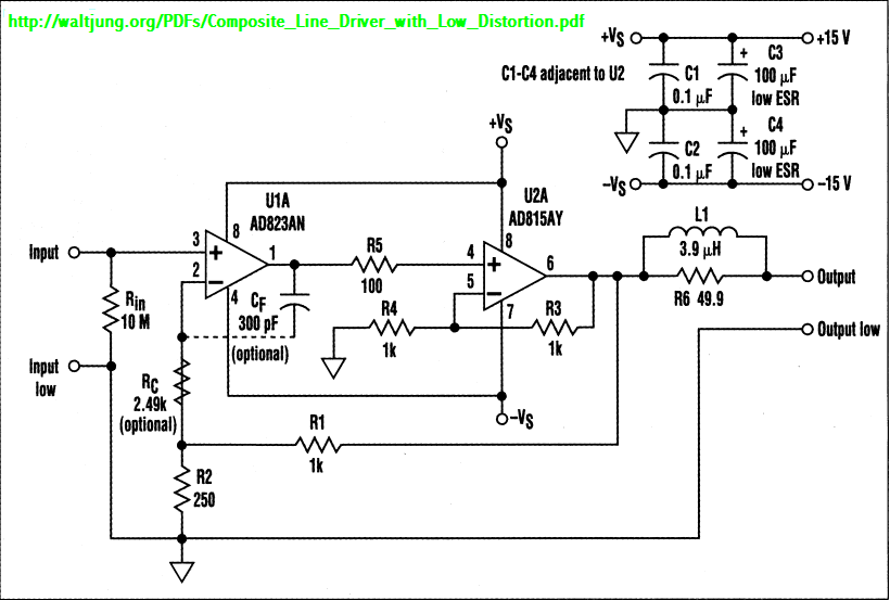
Buffering, and multiloop composite amps are promoted by Walt Jung as an easy way to improve op amp based amplifier performance:

http://waltjung.org/PDFs/Composite_L...Distortion.pdf

is pretty good for this headphone amp application, diy audio types should eventually read many more articles on his website as your electronic knowlege grows
 
Jul 19, 2007 at 3:14 PM Post #10 of 26
Quote:

Originally Posted by majkel /img/forum/go_quote.gif
I don't understand using LM6171 as a buffer. It is a nasty chip and it has limited current efficiency which screws up the buffer idea. Good and popular single buffer is OPA551, but you should use AD8397 which is dual and even more efficient than 2x BUF634. The only downside of using AD8397 is its hunger for power. 9mA per channel will spill up your battery pretty fast.


That OPA is pretty okay i guess (~200 mA output will be awesome
biggrin.gif
(and totally unnecisarily)
rolleyes.gif
), but the thing is, ...however, does anyone has a simple scheme to buffer the cmoy design ...

cmoyscheme.jpg


Where should i change the scheme and place the buffer?


Quote:

Originally Posted by NelsonVandal /img/forum/go_quote.gif
Why use two stages. You could use LM6171/2 as the only stage. Many amps are constructed that way. With 250Ω headphones, high current output is not essential.


You mean like a .. euh .. real CMoy?
 
Jul 19, 2007 at 3:25 PM Post #11 of 26
Use AD8397 alone in your CMoy.
POT - 10k log
C1 - use 1k resistor instead
R2 - not populated
R3 - 1.2k
R4 - 6.2k
R5 - 0 ohm will be OK (wire)

You can hear the higher current efficiency on PX100 compared to a plain op-amp, so what's the matter to limit your amp? If you buy 32-ohm Grado, 50 Ohm Senns or something similar, will you rebuild your amp then? This makes no sense. Parts working close to their current limits distort stronger than those more efficient, so there is no advantage besides power savings of using low output current op-amps.
 
Jul 19, 2007 at 3:31 PM Post #12 of 26
Ahum ... first: i cannot solder a SOIC, second i cannont solder SOIC's with a 30W tool.

And no, i dont have any friends
tongue.gif
biggrin.gif
.

Btw, the buffered Cmoy wont be my only amp, as i build a 'common' Cmoy too. I want to check if there are differences between an buffered one and a common cmoy. (their Power supply will vary too)
 
Jul 19, 2007 at 3:51 PM Post #13 of 26
Walt's article too technical?

his multiloop circuit:
jung_multiloop.png


many "audio" op amps work in U1A position (unity gain stable with GBW < ~ 1/3 U2 GBW), you could use your LM6171 in U2A position

You would probably want Acl ~10 (= R1/R2 + 1) and the local loop R3/R4 + 1 ~= 3
 
Jul 19, 2007 at 4:44 PM Post #14 of 26
I hope I didn't do something wrong, but i guess this will be a useable design ?
strangeamp.jpg


And should I use Walt's Resistant and Cap. attributes ?

Btw, which one is 'the buffer'?
 
Jul 19, 2007 at 5:40 PM Post #15 of 26
close but not quite right

Walt's "output low" is simply the ground return line, you need to take the amplified output from U2 buffer op amp output pin 6 through the load stabilizing network L1, R6 (L1 may be just a dozen turns of wire wrapped around the body of R6 - use the really old "carbon composition" type for R6 if you do this) L1 could be left out and R6 reduced to 10-20 Ohms witout much negative effect with 250 Ohm Headphones

Cf can save a unstable comination of too fast U1 so I would add place in a pcb layout for it but mostly not use it
 

Users who are viewing this thread

Back
Top