


bob808
New Head-Fier
- Joined
- May 20, 2013
- Posts
- 16
- Likes
- 10
Hello.
I need to design a LM338 regulated power supply for myself. I will be using it to power two small amplifiers that I have. One TA2020 and another TDA7297. The ta2020 requires about 13.5V and the tda7297 about 16V. I think that both should require a maximum of 2A, maybe 3A tops. I won't be using them at max since I have a pair of 96db spl speakers so it's mostly for relaxing not partying.
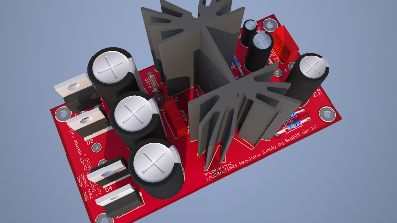
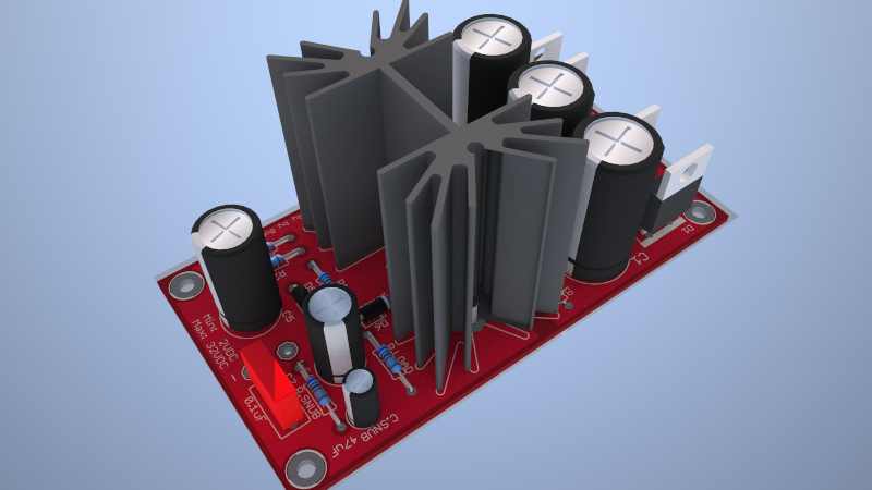
So I started to look for some schematics and I settled for LM338. I think it's ok for what I need and it's good practice in eagle") This is my first board design so please excuse any errors I've been making. I'm here to learn and make the pcb better if possible with your guidance. Also the board is free for anyone's use, as long as you're not making money off it
This is my first board design so please excuse any errors I've been making. I'm here to learn and make the pcb better if possible with your guidance. Also the board is free for anyone's use, as long as you're not making money off it
I will be posting the complete files for everyone.
So, I've also read this thread and inspired a couple of ideas:
http://www.head-fi.org/t/478881/lm317-dual-rail-power-supply
For LM338 the layout should be basically the same.
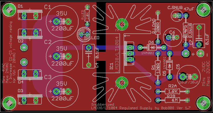
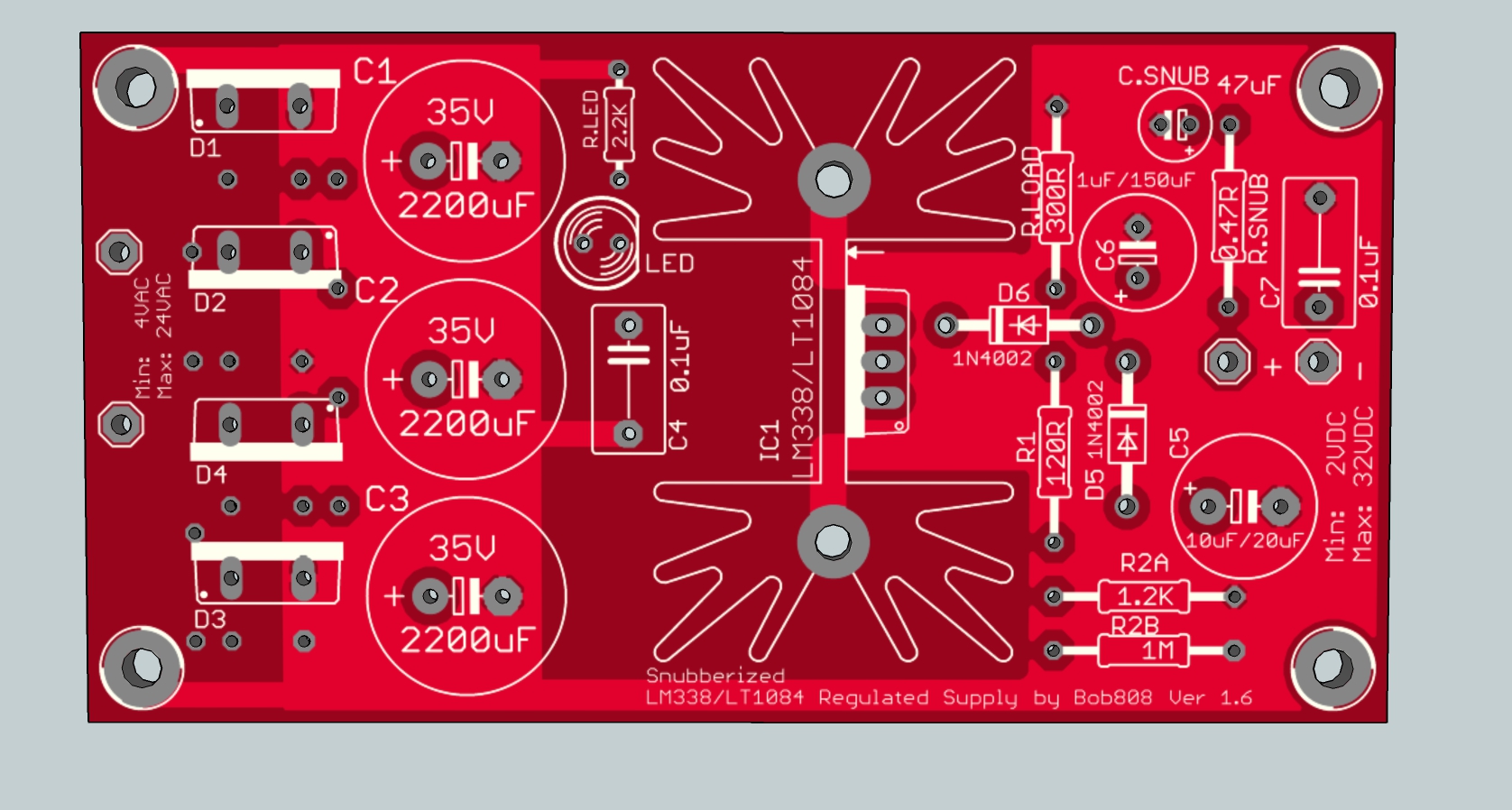
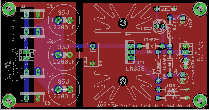
I've also included the option for LT1084 as it's similar, only has some different output capacitor requirements that I've tried to also note on the pcb itself. Also I've included the possibility to parallel two resistors to dial in the output voltage as close as possible. If you don't need it you can just leave it blank. The LED will probably be off the board anyway so I just placed it without much regard.
I'm using to220 diodes for rectification, I just noted them MUR860 as I've seen many people are using them, but I guess you could use any.
I don't know how critical the bypass is for the rectifying diodes, but I left it out. I only used a capacitor on the VAC line.
If you have any ideas on how I could make this board better you are welcomed!
Also I've tried to keep the board in the limit of 5cmx10cm so I fit in a price range when I'll be ordering them.
By the way, are there any companies that are cheap for 3-5 pcb production?
Hmm, seems I cannot add images/files.
Here are the links to the board and schematic pictures:
http://imageshack.com/a/img69/9069/9frb.png
http://imageshack.com/a/img834/6016/40z2.png
I need to design a LM338 regulated power supply for myself. I will be using it to power two small amplifiers that I have. One TA2020 and another TDA7297. The ta2020 requires about 13.5V and the tda7297 about 16V. I think that both should require a maximum of 2A, maybe 3A tops. I won't be using them at max since I have a pair of 96db spl speakers so it's mostly for relaxing not partying.
So I started to look for some schematics and I settled for LM338. I think it's ok for what I need and it's good practice in eagle
This is my first board design so please excuse any errors I've been making. I'm here to learn and make the pcb better if possible with your guidance. Also the board is free for anyone's use, as long as you're not making money off it I will be posting the complete files for everyone.
So, I've also read this thread and inspired a couple of ideas:
http://www.head-fi.org/t/478881/lm317-dual-rail-power-supply
For LM338 the layout should be basically the same.
I've also included the option for LT1084 as it's similar, only has some different output capacitor requirements that I've tried to also note on the pcb itself. Also I've included the possibility to parallel two resistors to dial in the output voltage as close as possible. If you don't need it you can just leave it blank. The LED will probably be off the board anyway so I just placed it without much regard.
I'm using to220 diodes for rectification, I just noted them MUR860 as I've seen many people are using them, but I guess you could use any.
I don't know how critical the bypass is for the rectifying diodes, but I left it out. I only used a capacitor on the VAC line.
If you have any ideas on how I could make this board better you are welcomed!
Also I've tried to keep the board in the limit of 5cmx10cm so I fit in a price range when I'll be ordering them.
By the way, are there any companies that are cheap for 3-5 pcb production?
Hmm, seems I cannot add images/files.
Here are the links to the board and schematic pictures:
http://imageshack.com/a/img69/9069/9frb.png
http://imageshack.com/a/img834/6016/40z2.png
