It is hard to build a Mini^3?

Mar 29, 2008 at 7:36 PM Post #16 of 28
Quote:

Originally Posted by Lil' Knight /img/forum/go_quote.gif
Sorry for my off-topic question
frown.gif

I've already had a Mini^3. I wonder if I want to make a balanced, is it possible?


http://www.head-fi.org/forums/f6/bal...ni-3-a-262816/
 
Mar 30, 2008 at 6:49 AM Post #18 of 28
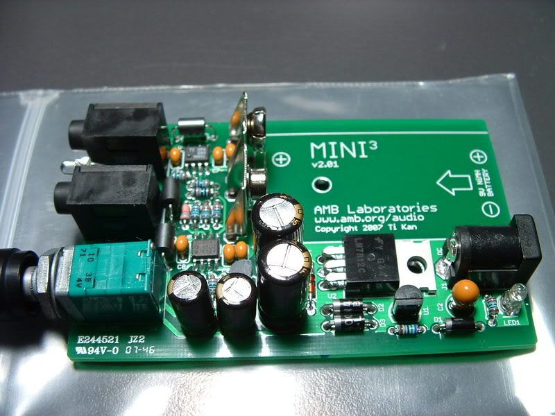
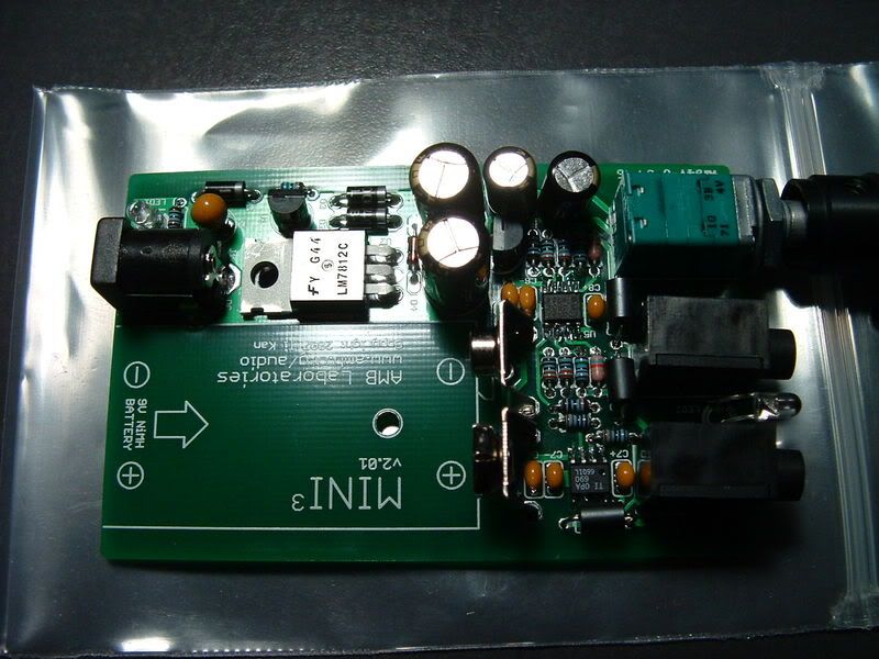
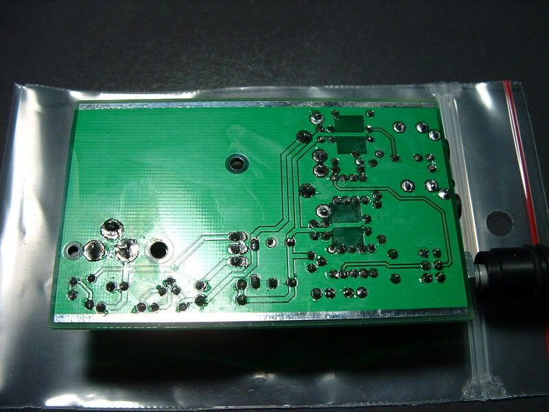
here's my first DIY amp ever. i never even built a CMOY. i have only soldered wires together before. I cant believe it actually worked perfect first time no issues! I am very comfortable with [construction] of SMD now. Time for a bigger project
smily_headphones1.gif
.

i used some cheap pliers, made in china multi meter (to ID resistors), regular tweezers, and a butane solder pen.

DSCF1126.jpg

DSCF1127.jpg

DSCF1128.jpg
 
Apr 3, 2008 at 2:31 AM Post #21 of 28
Sorry for the threadjack, but I just realized I forgot C2, the tantalum cap. Is there something I can sub for it (maybe a 100uF 25V electrolytic (C5) or a 1uF 35V tant/10uF 16V tant from ratshack)?
 
Apr 3, 2008 at 3:07 AM Post #22 of 28
If you must get something from RatShack, use the 1uF/35V tantalum. Don't use the 16V rated one because the wallwart could output more than 16V and tantalums often catch fire/explode when its ratings are exceeded (or if the polarity is reversed).
 
Apr 3, 2008 at 3:55 AM Post #23 of 28
Quote:

Originally Posted by amb /img/forum/go_quote.gif
If you must get something from RatShack, use the 1uF/35V tantalum. Don't use the 16V rated one because the wallwart could output more than 16V and tantalums often catch fire/explode when its ratings are exceeded (or if the polarity is reversed).


Ok. Will it make a big difference in using the 35V? Could I compensate by changing a few other values as well?
 
Apr 3, 2008 at 4:00 AM Post #24 of 28
Quote:

Originally Posted by seanohue /img/forum/go_quote.gif
Ok. Will it make a big difference in using the 35V? Could I compensate by changing a few other values as well?


No. That cap is merely a small filter/decoupling cap in front of the voltage regulators and the capacitance is not critical. I spec'ed 10uF/25V because it is the largest tantalum that would comfortably fit within that footprint and not cost an arm and a leg.
 
Apr 3, 2008 at 7:16 PM Post #25 of 28
Quote:

Originally Posted by amb /img/forum/go_quote.gif
No. That cap is merely a small filter/decoupling cap in front of the voltage regulators and the capacitance is not critical. I spec'ed 10uF/25V because it is the largest tantalum that would comfortably fit within that footprint and not cost an arm and a leg.


Ok, great. Thanks amb!

And for a quick sanity check, looking at the resistor pads, the one with the bar denotes the negative lead, right?
 
Apr 3, 2008 at 7:34 PM Post #26 of 28
Resistors can go in either way. The only orientation you may want to consider is which direction you'd like to read the colour bars, from left to right or from right to left. Either way they go in, they will work.
 
Apr 3, 2008 at 7:39 PM Post #27 of 28
Quote:

Originally Posted by joneeboi /img/forum/go_quote.gif
Resistors can go in either way. The only orientation you may want to consider is which direction you'd like to read the colour bars, from left to right or from right to left. Either way they go in, they will work.


Oh alright. Thanks!
 
Apr 3, 2008 at 11:32 PM Post #28 of 28
Quote:

Originally Posted by joneeboi /img/forum/go_quote.gif
Resistors can go in either way. The only orientation you may want to consider is which direction you'd like to read the colour bars, from left to right or from right to left. Either way they go in, they will work.


You know, I just reread that and I can't believe I said resistor lol. I meant LED. But I figured it out.
 

Users who are viewing this thread

Back
Top