rds
Headphoneus Supremus
- Joined
- May 4, 2008
- Posts
- 2,045
- Likes
- 31
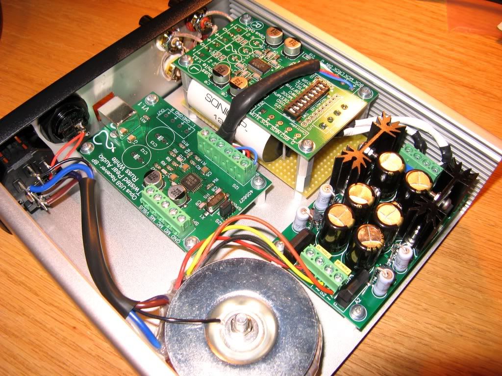
If you think the case should not be grounded this way (ie to the transformer bolt) please be specific as to why this is a problem in this build.
| Originally Posted by Leny /img/forum/go_quote.gif If the other end of the wire touches the case it effectively creates a 'shorted turn' around the transformer, and you can guess the rest... Do not do it! |

| Originally Posted by dBel84 /img/forum/go_quote.gif ps - nice build btw |

| Originally Posted by digger945 /img/forum/go_quote.gif Have you listened to it yet? |

| Originally Posted by Hayduke /img/forum/go_quote.gif By attaching the wire to the mount, you are placing it very close the transformer. Knowing how a transformer works, it's easy to see why it would be a major cause of EMI and introduce noise to the signal. I'm not saying that in your pic, there is a problem. Again, like I said in the other thread, if nothing is too hot and it sounds good to you, then enjoy it and don't worry about it
|

| Originally Posted by MoodySteve /img/forum/go_quote.gif Agreed - your build is nicely laid out and attractive. Well done! |
| Originally Posted by MoodySteve /img/forum/go_quote.gif I wanted to reply to a few comments that you made in 'that other thread'
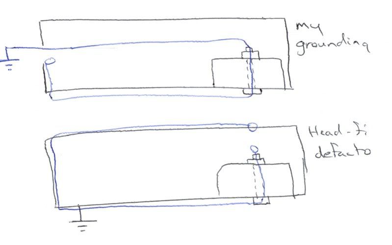
1. 'It doesn't matter where you ground the IEC to the chassis' -I assume you are not referring to a circuit with a star ground... |
| Originally Posted by MoodySteve /img/forum/go_quote.gif 2. 'I chose the transformer bolt for the lowest impedance path to the chassis' -If you're after the lowest impedance path, why not just crimp a ring terminal on the end of the wire and bolt it right to the chassis? Also, I'm surprised that you measured the transformer bolt as having lower impedance than the standoffs. Regardless, bolting directly to the chassis will have lower impedance than going through a bolt or standoff. |
| Originally Posted by rds /img/forum/go_quote.gif Also, no offense personally, but please no statements of "DON'T DO IT" etc. I'd like this to be about learning and not dogma. |
| Originally Posted by rds /img/forum/go_quote.gif It is just a better mechanical connection in my opinion. Also, see my comment about 'safety feature' above. Besides that it allows for a neater layout. |
| Originally Posted by MoodySteve /img/forum/go_quote.gif I hope you're not referring to your fuse as the 'safety feature'; relying on a fuse for fault protection is never a good idea. |
| Originally Posted by MoodySteve /img/forum/go_quote.gif I agree with Leny - there's just no real reason to ground the IEC there - it achieves what can be easily achieved elsewhere but poses an unnecessary (albeit extremely unlikely) risk. |
| Originally Posted by MoodySteve /img/forum/go_quote.gif I think your signal wiring and transformer location is optimal, although there will be an orientation of the transformer that has minimum induced noise (in theory - if it's all below audibility you could argue it's just numbers). Please don't get me wrong - this is a great built - we're just trying to make it greater-er
|
| Originally Posted by rds /img/forum/go_quote.gif No, after all it only works if the broken ground touches the case. That would be a terrible thing to rely on. |
| Originally Posted by rds /img/forum/go_quote.gif I have taken a course specifically on (electrical) medical equipment design (where standards are particularly stringent), and never once did I hear mention of considering what might happen if a layperson opens up and starts messing with a power supply. |
