IEC power entry module wiring question
Jan 23, 2010 at 5:07 PM Thread Starter Post #1 of 9

OliG

New Head-Fier
Joined
Feb 18, 2008
Posts
10
Likes
12
Hi,

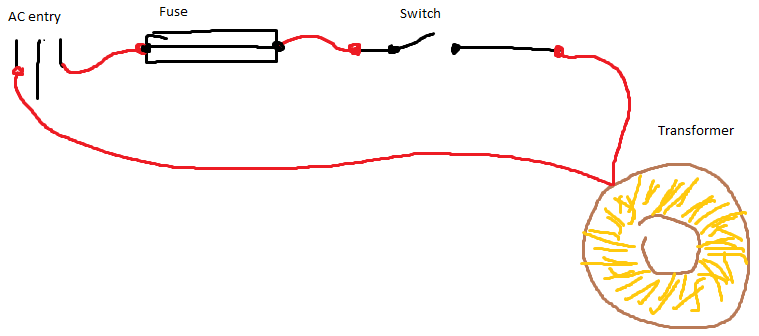
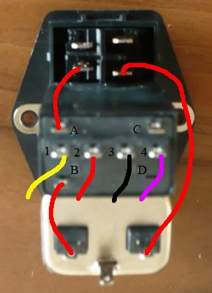
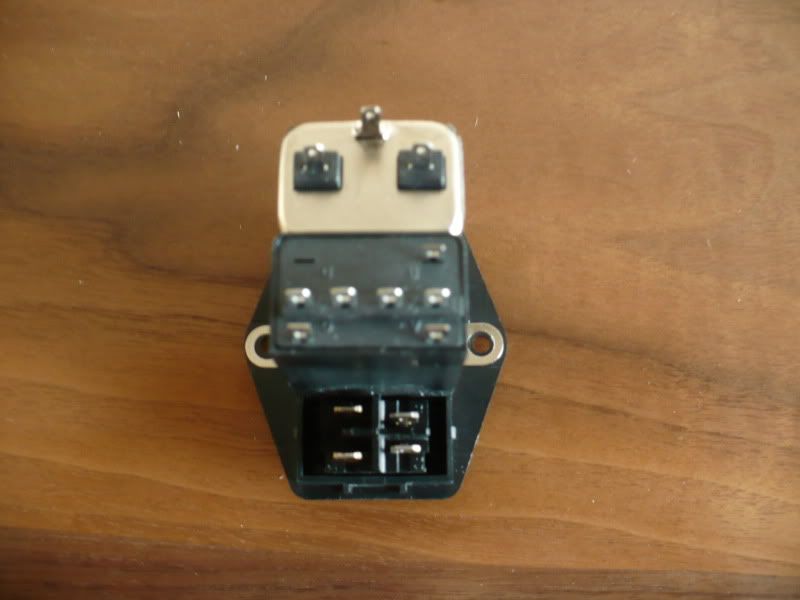
I am ready to do the wiring on my CKKIII, but I have a question concerning the IEC module I bought. It include a double fuse drawer, a switch and it is emi filtered. The thing is that the entry, the fuses and the switch have to be wired separately, and Im not sure how to do this, because the fuse drawer has 7 connections :

P1010307.jpg


I bought it from digikey, here the link :
Digi-Key - 603-1149-ND (Manufacturer - 10SB3S)

So, how should I wire this? I guess I connect the entry to the fuse and the fuse to the switch, but Im not sure about the fuse part.

Also, Do I need both fuses?

Thanks !
Oli
 
Jan 23, 2010 at 5:21 PM Post #2 of 9
Are you sure you are not missing part of the IEC? Like the back box of it?

Seems like it defeats the purpose of buying and All in One IEC if you still have to wire it up. The IEC I have has a fuse drawer and switch builtin and I did notice that the back panel of it will unsnap so is it possible you were sold half of the IEC?
 
Jan 23, 2010 at 6:28 PM Post #3 of 9
Hello,

Yeah Im pretty sure nothing is missing I just unpacked it and I didnt lost parts, also if you look at the datasheet the module seem complete. I also find this really strange that I need to make connections...

Would this make sense to you if I check with a multimeter wich pins of the fuse drawer conduct if the fuse is inserted, and if they dont conduct without it, that would be the 2 correct pins to get the fuse safety?

Also, Is it the correct way to connect all this together :
(entry -- fuse -- switch)
(I know... I have terrifics paint skills
wink.gif
)

dessin.png


Thanks again,
Oli
 
Jan 23, 2010 at 6:59 PM Post #4 of 9
Well your plan would work but you need to handle those other pins if the are also hot.

I do not think you lost any parts I think they might have sent you an incomplete part. Or maybe sometimes these parts are meant to be used with another part that you are suppose to buy seperately.
 
Jan 23, 2010 at 11:14 PM Post #5 of 9
There is only one fuse and the "fuse drawer" serves double duty as a voltage selector, which is why it has 7 terminals.

Did you notice how the letters and numbers that are molded into the "fuse drawer" correspond with the letters and numbers from the schematic included in the datasheet?
wink.gif


helpnz.png


help2y.png


I did not label pins 1,2,3 and 4 because you can hardly see them in the picture...
 
Jan 24, 2010 at 2:49 AM Post #6 of 9
Hello,

I did noticed the letters on the diagram but I didnt know a fuse was represented like this (tought it was represented like I draw in 3rd post... yes Im a newbee), so I was a bit lost. And now that I know that, Im still confused... If I understand the diagram corectly, I should connect L to B, A to the switch, switch to N and the 4 primaries of the transformer to the 1-2-3-4 terminals? is this correct?

I'm using the toroidal transformer recommended by Amb for the ckkiii, the datasheet is here :
http://rocky.digikey.com/WebLib/Amve...ansformers.pdf

"For 115V operation, connect primaries in parallel by connecting yellow and
red lead wires together and black and violet leads wires."

So here it is as a picture is worth 1000 words :
(wires to 1-2-3-4 terminals comes from transformer)

connection.jpg


Does it make sense?

I think this is a quality IEM so I would like to use it but I want to be 100% sure I will wire it corectly. Else im gonna use a cheaper iem and a switch I bought today... Not as good but I will know how to make them work.

Thanks for all the help !
Oli
 
Jan 24, 2010 at 5:19 AM Post #8 of 9
Thanks MisterX,

So I guess I should follow my first idea and connect the transformer in parallel, one end going to L and the other to the switch. But in that case, what is the purpose of the terminals 1-2-3-4?

Oli
 
Jan 24, 2010 at 11:01 AM Post #9 of 9
Terminals 1, 2, 3 and 4 service the input voltage selector.
It appears that you can simply remove the "fuse drawer", turn it around and stick it back in to change from 112 to 240 volts (changes from the primaries from wired in parallel to the primaries wired in series).
 

Users who are viewing this thread

Back
Top