IC: DIY spdif switcher
Jan 9, 2009 at 6:37 PM Post #16 of 56
Quote:

Originally Posted by cetoole /img/forum/go_quote.gif
I guess that was basically my point, its a great receiver, but Wolfson, in their infinite wisdom, decided to make it reliant on a uP if you want to use more than one input. I know you are a software guy, and figured you would already have some kind of processor in here for use with the remote, so put two and two together to get five.


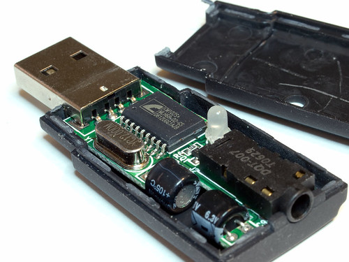
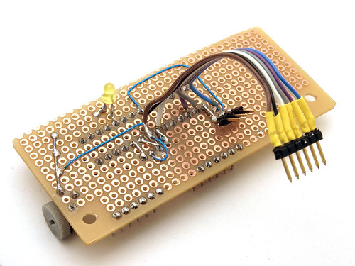
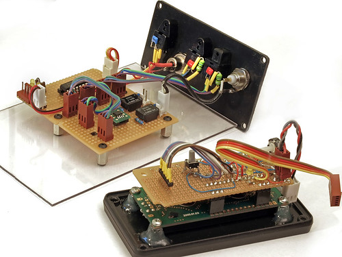
here's the 'processor' I'll be using:

3140217202_96f94f8e16.jpg


link:

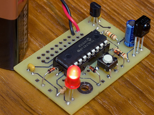
TinyIR2 Learning IR remote control receiver

its a black box - no source code, of course ;(

it gives me active-high outputs and I 'take it from there'.

that's life in the integration business - you often don't have access to other internals and HAVE to view things as 'velcro integration' so to speak
wink.gif
 
Apr 15, 2009 at 2:17 AM Post #18 of 56
update: the proto works. it was simple, like I had hoped (planned. no, hoped, really)
wink.gif


3442643821_4d79813756_o.jpg


3443461806_a013b18c45_o.jpg


just a 4052 analog switch (using half of it) with toslink opto blocks in and 1 going out.

the usual choke/cap bypass for the toslinks is there.

no reshaping at all. just real low-budget 'does it work' testing.

it seems to work. and given how good modern dacs are, I'm not 100% convinced its worth 'prettying up' the signal any more than it is now. I'm getting lock and I'm hearing sound. that's at least a good start
wink.gif


for testing I'm using back-to-back gamma1 dacs. one is a half build (just the usb/spdif board) and that gets me opto-out from my pc. I go into this switch and then out of it into another Y1 dac that takes opto-in spdif and makes analog sound from the other end
wink.gif


dial in a 2 bit binary address and the right input port is mapped to the single output.

$20 or less in parts.

perhaps I'll work this up into a proper project. I've now learned how to deal with controllers and lcd displays (and IR remotes) and so just having a remote controlled user-label display that picks digital inputs - that could be cool just on its own (?)
 
Apr 15, 2009 at 3:03 AM Post #19 of 56
Wow totally cool !!!

I love following your projects in the hopes of learning some of this stuff
smily_headphones1.gif


On the 1 out jack how hard would it be to use a combi jack (SPDIF and Optical ?) like the one used on the Auzen Prelude SC digital output ? It would mean using a plastic adapter for Toslink out but you could use a SPDIF as normal without much or any SQ loss.

Of course it's just something that occurred to me while reading this thread that might give you some additional flexibility provided the additional circuitry can be incorporated. Maybe 1 in and 1 out using the combi jack ? I have no idea what part number that is or where to source one. It seems to do a very good job with the Auzen card. I can get a solid 24/96 signal lock via Tolsink using a plastic fiber cable NP whatsoever to the HT processor 3m away using this jack (same goes for SPDIF coax).

If this idea (is lame and) counterproductive to what you are trying to do please forgive my lack of knowledge and experience and go easy on me
redface.gif


Peete.
 
Apr 18, 2009 at 12:01 AM Post #20 of 56
Grats on getting on HackaDay
wink.gif


Personally I've never worked with that PIC before (only worked with the PICAXE so far) but it looks like he may have given enough information to allow reverse engineering of the code.
 
Apr 18, 2009 at 12:24 AM Post #21 of 56
Quote:

Originally Posted by Pricklely Peete /img/forum/go_quote.gif
Wow totally cool !!!


thanks
wink.gif


Quote:

On the 1 out jack how hard would it be to use a combi jack (SPDIF and Optical ?) like the one used on the Auzen Prelude SC digital output ? It would mean using a plastic adapter for Toslink out but you could use a SPDIF as normal without much or any SQ loss.


sounds like something like this?

3133407129_61876871c9.jpg


3133406953_09f0fa2abf_o.jpg


that's a combo opto+coax jack. tricky stuff!
wink.gif


if the connector is buyable, sure, why not. its only a physical layer thing - the bits are the same.

I'm thinking about how to best give flexibility in 'physical jacks' and try to decouple that from the main board design.
 
Apr 18, 2009 at 12:27 AM Post #22 of 56
Quote:

Originally Posted by Gatsu /img/forum/go_quote.gif
Grats on getting on HackaDay
wink.gif


that blew me away - I had no idea at all
wink.gif
I noticed a HUGE spike in my view-count on flickr and it wasn't until someone replied on that photo that it was on H.A.D. ha!
Quote:

Personally I've never worked with that PIC before (only worked with the PICAXE so far) but it looks like he may have given enough information to allow reverse engineering of the code.


no need to reverse engineer, the source will be coming along with schematics. first, though, some testing has to be done. it passes the 'yup, bits are flying' test but I'd like to do a bit more test equip-level testing before throwing out circuits. so far, I'm encouraged but I know the crowd here is mighty picky about their bit accuracy (lol). more testing is needed but it does look good, so far.
 
Apr 18, 2009 at 12:32 AM Post #23 of 56
new photos of the thing being 'bits in flight' tested:

3447797560_a494b5ce20_o.jpg


here is my first test, going across media types going from a gamma1 'lite' (usb to spdif), thru the switch and then out via opto to a full gamma1 dac.


3447531579_8da510378c_o.jpg


3448208129_078d7cd4e7_o.jpg


the wiring isn't exactly to-spec (LOL!) but I'm just doing INFORMAL testing at this point. the last 2 pics show it going from coax up to TTL level (for the switch), thru the switch chip and back down to coax level (half volt) again. source was my 'popcorn hour' media streamer and sink was my m-audio superdac2496 (many years old AKM-based dac). bits flew and I heard the music just fine.

until the battery died.

and then it was jumper cables for the rest of the nite
wink.gif
 
Jul 28, 2009 at 6:00 PM Post #24 of 56
Nice switch linuxworks. Do you know if the digital-analog-digital conversion affects the bit stream? That is, have you tried passing encoded audio through the switch without breaking it (like DTS or DD)?
 
Jul 29, 2009 at 4:33 PM Post #25 of 56
Quote:

Originally Posted by TeraHz /img/forum/go_quote.gif
Nice switch linuxworks. Do you know if the digital-analog-digital conversion affects the bit stream? That is, have you tried passing encoded audio through the switch without breaking it (like DTS or DD)?


it cannot affect it. not in *this* switch.

this switch does not go above the PHY (physical) layer. it does not 'unwind' packets or understand them at all. nothing is edited or changed. its just a physical repeater, not even a real bridge (in the datacomm sense).

since dts and dd5.1 don't use enormously higher data rates than normal old spdif, I'm sure they will be as bit-perfect as pcm, thru a switch like this. in fact, dts will refuse to 'run' if it gets less than bit-perfect data presented to it (same with dd5.1, I think). so if you get a signal 'lock' light, at all, you're golden.
 
Jul 29, 2009 at 4:42 PM Post #26 of 56
I should update this thread. I think I even forgot about it
wink.gif


here's what I have, right now, on this spdif project:

I re-did the coax-in section. in fact, I'm making this a very modular design so you (the builder) can pick what options you want and not have stuff you didn't.

here's the coax-in 'port board' in proto form:

3733647912_9faf014eeb.jpg

3733647420_efb5551174.jpg


parts needed for it:

3732616997_8496ba467b.jpg


and there is is, being tested (it works):

3733885306_0b2039f4d5.jpg


that's the coax-input board (with 2 independant ports).

now the switch guts, the 'fabric' as its sometimes called:

3743480917_d65966678c.jpg


and the initial wiring, just getting started
wink.gif


3744274932_35bcba3249.jpg


this is where the switching happens. this chip supports up to 8 input ports. I am going to build for 4 (the row of 4 red headers). it supports 1 ttl output which directly drives opto-out and can drive a coax-out in a similar board fashion like the coax-in board.

here's an opto port; there's little point in this having its own 'board' so I air-wire it and secure it (well) to the rear panel with a screw. much better than board mounting even though its a lot more work:

3744675446_853c02c13b.jpg

3743880507_ab799a2138.jpg


that mostly covers the switch and its i/o 'port boards' (or flying ports, in the opto case, lol).

next post has some info on the cpu controller that is made for this.
 
Jul 29, 2009 at 4:49 PM Post #27 of 56
here's the controller photos, also using proto board (no pcb designed. yet.)

3737011320_45ab6bc16b.jpg

3736218541_ee3dbb22f8.jpg

3736218797_a7f05fefeb.jpg

3737012106_7d009bf4e5.jpg

3737012428_04d7837624.jpg

3737012730_e097d6d931.jpg

3736220011_81353923ab.jpg

3736220415_6f538c3f9e.jpg

3736702297_d8da8e3889.jpg

3736701185_dda15ec1aa.jpg


3739320504_bf9669102b_o.jpg


3739662095_fa24d5362c_o.jpg


this sort of turned into a project all in itself
wink.gif
but from it comes a general purpose i/o (lcd, IR remote) board that I can re-use in all my other DIYs.

here's where I used it, to integrate some functions in amb's latest y2 (gamma2) dac:

3759903605_8934b9b90b.jpg


3763761604_542249037b.jpg
 
Jul 29, 2009 at 5:01 PM Post #28 of 56
Quote:

Originally Posted by linuxworks /img/forum/go_quote.gif
this switch does not go above the PHY (physical) layer. it does not 'unwind' packets or understand them at all. nothing is edited or changed. its just a physical repeater, not even a real bridge (in the datacomm sense).


Very cool! Thanks for updating the thread as well. This is my next project (after the y2 is finished)!
 
Aug 4, 2009 at 4:16 AM Post #29 of 56
more updates
wink.gif


3786964219_c77488a4e5_o.jpg


3787776832_d76837c17b_o.jpg


I'm happy enough with this build
wink.gif


I also found a local source of opto-in parts (8mhz, old style, but they work at redbook audio rates just dandy). I may grab some extras in case people want them; when you build switches, you often need lots of parts for ports. lucky that I found some input ports since you need more of those than output ones
wink.gif


so, this is the main switch fabric board. you send in 2 or 3 bits of constant 0 or 1 on each of the wires and the binary-numbered input port is connected to the single output.

you don't really even need a controller. if you are ok with just having 2 switches and using binary to select the 4 states, hey, have fun, the circuit will work fine just the same
wink.gif


but for just a bit more work, the lcd and IR front-end can be integrated and that will select the 2 or 3 bit binary address for you, in a nice friendly way.
 
Aug 6, 2009 at 3:37 AM Post #30 of 56
more updates
wink.gif


3792807396_5f06557ec9.jpg


3792470626_5987ef5b97.jpg


3791489794_5c07401a01.jpg


3790677017_2b0a46b055.jpg


3791489312_e527ba1f27.jpg


3791489144_019e720e5f.jpg


3790676325_5a25153489.jpg


3791488712_d3834cb73d.jpg


informally, it seems to work. I'll soon begin some scope level testing to see what the waveforms really look like, just out of curiousity. but for practical use, I see no reason to not use something like this. I've been using the previous version for a while, now, and I'll start using this version now that its all boxed up. I don't hear any sonic problems; it just seems to pass the bits thru unharmed.

I'll have SPDIFmaster at the bay area meet (this saturday) in case anyone local wants to come check it out
wink.gif
 

Users who are viewing this thread

Back
Top