I Hate Soldering OPAMPS!!!
Feb 4, 2010 at 8:00 PM Post #16 of 25
You have to come up with a procedure and techique that works for you. You will only learn by doing and it take much practice to get really good.

I suggest you try with cheaper opamps and circuit to get the technique down before you move onto more expensive circuits and opamps.
 
Feb 5, 2010 at 1:02 AM Post #17 of 25
Quote:

Originally Posted by ROBSCIX /img/forum/go_quote.gif
You have to come up with a procedure and techique that works for you. You will only learn by doing and it take much practice to get really good.

I suggest you try with cheaper opamps and circuit to get the technique down before you move onto more expensive circuits and opamps.


You're right, I have a good combo lamp /magnifier and helping hands. I get most of them on with what I consider a decent flow (some may cringe) but then I'll get one that drifts to the other leg and those who have worked with the mini's opamps know how close they are togther. Trying to remove the solder seems to make it worse. At that point I've resorted to a straight edge blade and sliced the joint. I should finish this over the weekend, I'll post pix of the board with or without the smoke!
wink.gif


Thanks to all for the links and input, the newbie appreciates it!
k701smile.gif
 
Feb 5, 2010 at 1:32 AM Post #18 of 25
My suggestion:

Tin two pads in opposite corners, then place your opamp. Reheat one of the pads to secure one side, then line everything up. Once things are lined up, tack down the second side, and continue to solder down the remaining pins.

I'll usually solder down the rest of the pins using a needle-point tip on my iron, then break out a larger tip and use a solder wick to remove any overflow.

I've done a few Mini^3s, a few DACs, and some other random gear using this method.
 
Feb 5, 2010 at 2:31 AM Post #19 of 25
Quote:

Originally Posted by motherone /img/forum/go_quote.gif
My suggestion:

Tin two pads in opposite corners, then place your opamp. Reheat one of the pads to secure one side, then line everything up. Once things are lined up, tack down the second side, and continue to solder down the remaining pins.

I'll usually solder down the rest of the pins using a needle-point tip on my iron, then break out a larger tip and use a solder wick to remove any overflow.

I've done a few Mini^3s, a few DACs, and some other random gear using this method.


This is pretty similar to what I do. I place the IC with tweezers and get it lined up with all the pads, then flip them around and use the blunt end to press down on the IC while I solder one pin. After that I'll do the remaining pins. For larger SMD stuff like SOIC I just use the standard tip on my Hakko 936 and go pin by pin, any smaller and I'll usually flood and suck.
 
Feb 5, 2010 at 2:09 PM Post #20 of 25
My method works great for me,

1, use a needle point tip on the iron and KEEP IT CLEEN!!!!!
2, use .032 ( or smaller if you can find it )dia. solder, available at radio shack
3, This is a HUGE help, use the flux thats also available at radio shack, its kind of a gell, comes in a small tub.

then, to start soldering the opamp,

1, clean your tip
2, dip the solder into the flux, get a good gob of it on the end. Use this to aply a good ammount of flux all over the pads of the PCB, get a good amount of it smeared all around. The more the better, helps hold the chip in place.
3, put a small bit of solder to the tip of the iron, then touch one of the pads, the solder should wet the pad.
4, put another bit of flux back on that pad
5, now place the opamp (using tweezers or the like, I prefer to just use my finger tip,) get it where you want it and apply heat to the previously wetted pad. you should see the soder just wick rught up the leg of the opamp.youl also feel the amp seat flat on the board.

6, now apply another bit of solder to the tip, and touch it to the opposing leg, solder should wick right up that one.

7, repeat step 6 for the rest of the legs.

then I will usually check and re-flow the pads all again to ensure they have an adequate ammount of solder, By using generous ammounts of flux, and just wetting the tip of the iron, its very easy to avoid solder bridges.

The flux does have its draw backs, its messy and sticky, But it makes My SMD joints come out great.

also , if you do get a bridge, dip some solder wick into the flux, and it will pull the solder right up off the board.

I have no problems at all even with the finer pitched IC's using this method.
 
Feb 6, 2010 at 2:24 AM Post #22 of 25
Quote:

Originally Posted by H22 /img/forum/go_quote.gif
My method works great for me,

1, use a needle point tip on the iron and KEEP IT CLEEN!!!!!
2, use .032 ( or smaller if you can find it )dia. solder, available at radio shack
3, This is a HUGE help, use the flux thats also available at radio shack, its kind of a gell, comes in a small tub.

then, to start soldering the opamp,

1, clean your tip
2, dip the solder into the flux, get a good gob of it on the end. Use this to aply a good ammount of flux all over the pads of the PCB, get a good amount of it smeared all around. The more the better, helps hold the chip in place.
3, put a small bit of solder to the tip of the iron, then touch one of the pads, the solder should wet the pad.
4, put another bit of flux back on that pad
5, now place the opamp (using tweezers or the like, I prefer to just use my finger tip,) get it where you want it and apply heat to the previously wetted pad. you should see the soder just wick rught up the leg of the opamp.youl also feel the amp seat flat on the board.

6, now apply another bit of solder to the tip, and touch it to the opposing leg, solder should wick right up that one.

7, repeat step 6 for the rest of the legs.

then I will usually check and re-flow the pads all again to ensure they have an adequate ammount of solder, By using generous ammounts of flux, and just wetting the tip of the iron, its very easy to avoid solder bridges.

The flux does have its draw backs, its messy and sticky, But it makes My SMD joints come out great.

also , if you do get a bridge, dip some solder wick into the flux, and it will pull the solder right up off the board.

I have no problems at all even with the finer pitched IC's using this method.


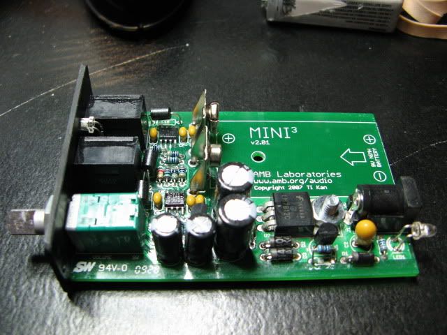
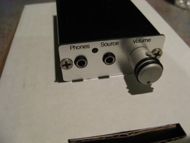
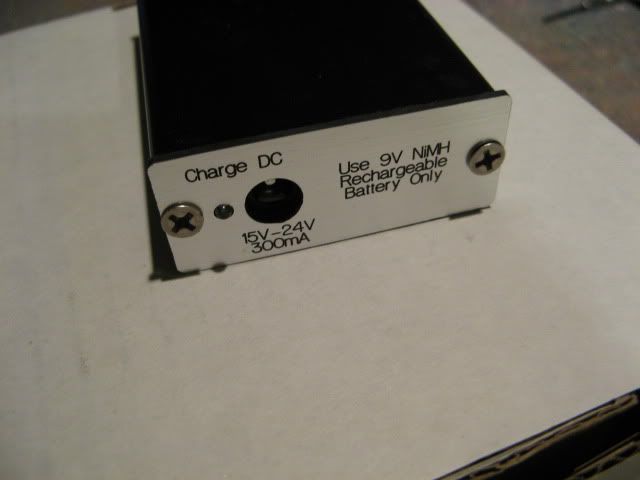
Thanks, I'm condensing and printing everyone's suggestions .... the good news is I finished my first Mini3 AND IT WORKS! OMG I cannot get over the quality of the sound. I used the ops for the high performance model and 51ohm resistor in the charging circuit. It could use a little more gain for the AKG702's but the Grado 325'is sound awesome thru it. I still can't get over the sound it puts out .....

I am very glad I built this, now I'm off to order three more boards and 20 opamps so I can complete #2!
wink.gif

I'll post the rest of the pix in the build thread ...
biggrin.gif


IMG_1277.jpg


IMG_1286.jpg


IMG_1284.jpg
 
Feb 6, 2010 at 2:28 AM Post #23 of 25
I like the front and back panels! Where did you get them?
 
Feb 6, 2010 at 5:09 AM Post #24 of 25
Made them at work compliments of the machine shop. They're plastic ... we tried to use black/white/black phenolic but it's too brittle and kept chipping at the screw holes so we went with softer material. I probably could have cut aluminum then powdercoat and etch but it was getting time consuming for a "goverment" project.

I didn't want to "borrow" the AMB labs logo on material Ti didn't provide so we left it off.
But everyone knows it's a Mini3!
 
Feb 6, 2010 at 1:44 PM Post #25 of 25
Nice looking amp! glad you like the sound of it. I now Have 4(!!!!) mini 3's well, 5 actually.

3 (2 HP and one long run time) I bought from AMB. (the reason I have 2 HP's is I temporarily lost one...)

then the DIY bug hit me so I designed one that is ultra small, size complimens my Clip+.

Still waiting on some components, but it sounds good to, cant wait to do a comparison to My AMB board's. hopefully I did a good enough job laying out the board that its close in SQ!
 

Users who are viewing this thread

Back
Top