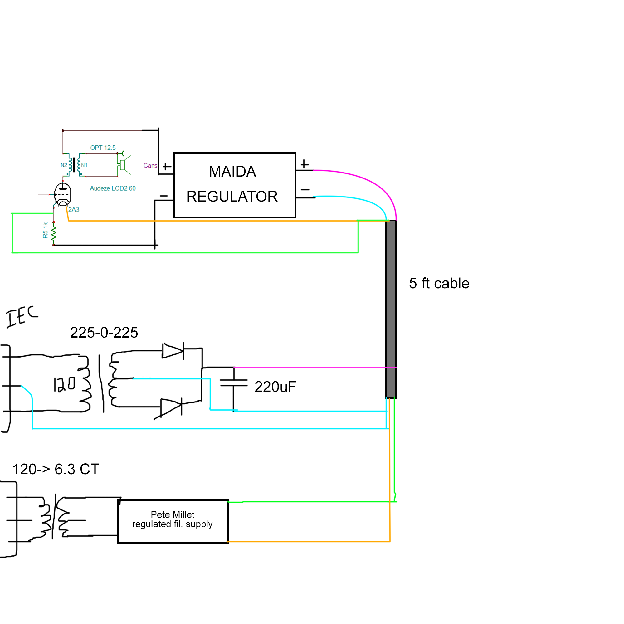
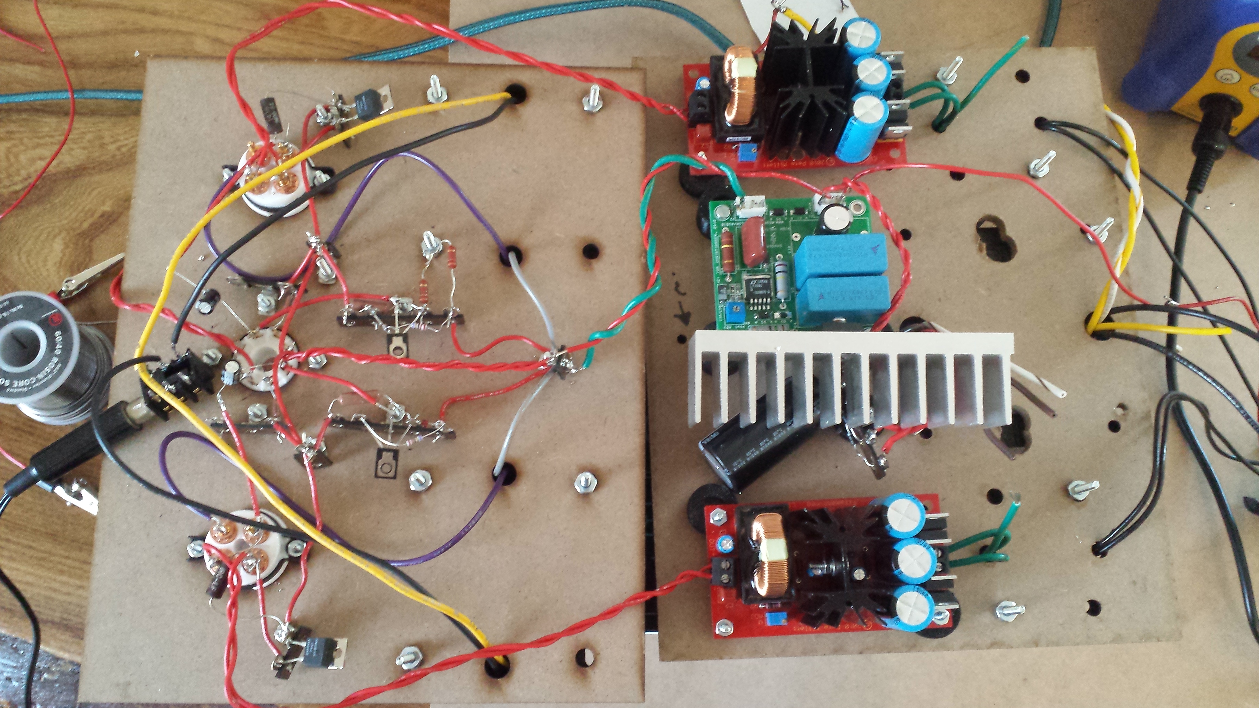
So even though all my grounds sort of "feed" in to the main grounding star it is causing ground loops? I thought a ground loop occurred only when the same component had 2 paths to ground, which it doesn't seem like. How should I re-ground it to fix the issue?
Without doing a major chassis rebuild, my suggestion is to run a ground wire from each component that needs a ground to a central ground. Quick and easy way to do this is the following:

To further explain what's going on, I found some pictograms. Just ignore all of the amateur radio stuff and imagine each of your components. Shamelessly stolen from
http://kc.flexradio.com/knowledgebasearticle50426.aspx

That is bad. What's happening is the PC is getting a different ground reference than the Transceiver, and the rest of the "chain" of equipment.
A single point ground, like this:

Will reduce the relative ground reference between each component, which is what causes your hum and "ground float."
Hopefully my unrelated examples will help you understand what's going on. What I'd do is put one of those grounding bars (found at your local home depot, lowes, or electrical supply store) and connect earth to that, then run a wire from each component to that bar.
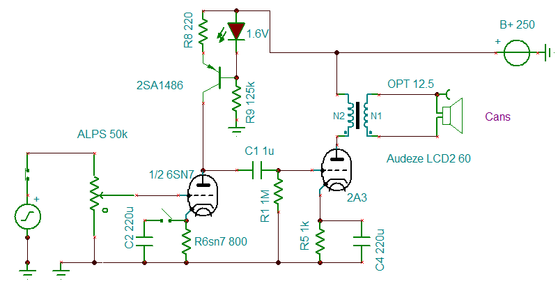
If you were to build a new chassis, or place everything on a plate of steel or aluminium (I don't suggest Al, because of corrosion and the galvanic effect), you would just tie everything directly to the chassis which is connected to ground. You would then have the shortest possible ground path internally, which would reduce all of the harmonic issues (which you probably won't have with an Audio Spectrum amplifier anyway, but good practices remain.)
Hopefully everything made sense, if not I'll do my best to answer your questions.