How to measure power supply noisefloor
Nov 28, 2009 at 10:39 AM Post #17 of 33
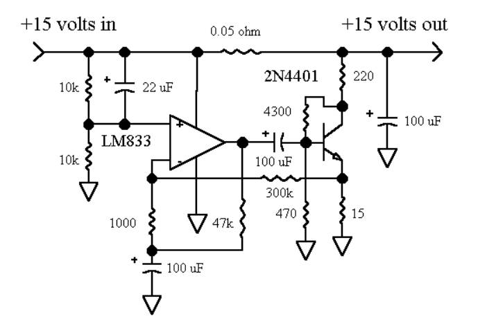
Nice job Frex. Can you please link to a schematics of the NR section you've used?

It does a great job of removing noise. Is it limiting the maximum output current/inrush current somehow?
 
Nov 28, 2009 at 12:30 PM Post #18 of 33
amb, i will try to find this regulators for test it.
But, i think the result will be nearly the same.


KT88, the schematic of noise reduction system used:
NRschematic.jpg

More info about this circuit at Library
I have simulated this circuit (before wiring) with Microsim PSpice, and it work fine. In my circuit board, the AOP used is a LT1115 because it have less noise and higher bandwith. The best results is done with the LT1028 or AD797.

This circuit doesn't really affect the output current of the regulator.
But the serial shunt (low value) can change the transient response.
However, good transient response is reached primarily using local decoupling near each IC.


Frex.
 
Nov 28, 2009 at 8:20 PM Post #21 of 33
glt,
I know this application note.
You can easily calculate the output of this circuit if it's voltage noise is ~6nV/sqrtHz. 6e-9 x sqrt(100kHz)=1.9µVrms. (3.3V)
It is a good approximation (spectral noise density varies with frequency).
This level of output noise is very good.
Beware, here the voltage noise is given for a low output voltage (3.3V).
The output noise is proportional to the closed loop gain.
For a 15V operation, the output noise will be multiplied by the ratio !
So you have now ~ 8.6µVrms (1.9µV x (15/3.3)).
Sorry, i don't have those parts for test it.
smily_headphones1.gif


Frex
 
Nov 29, 2009 at 1:11 AM Post #22 of 33
The test load is 100 ohms and test current 150mA?(sorry if I got this wrong)

Have you tried any tests with a switching load, like a transistor or mosfet, or an ampifier of some kind with a load connected to the output?

Have you ever tried to parallel 3-pin regulators to see what happens?

Just curious. I'm in the middle of testing some different kinds of power supplies to see how stout they are as a load is switched on and off at audio frequencies. Rather crude, I know, but I'm coming up short on information about power supply testing and evaluation.
 
Nov 29, 2009 at 6:20 AM Post #23 of 33
Quote:

Originally Posted by frex /img/forum/go_quote.gif
It's a low noise high gain amplifier with band-pass filtering (10Hz-100kHz ). The amplifier gain is 80dB (10000x) in frequency range, and it's own noise is only 500nVrms (-127dbVrms), with it's input shorted by a 50Ohms plug. (This amplifier is fully decribed in the AN83 from Linear Technology).


The AN83 amplifier has 60dB gain. What did you change to get 80? If you increased that first feedback resistor by 10x, that puts a lot more Johnson noise in the first stage. If you added another stage, that adds noise, too. The best place to make a change would be to increase the gain of the final stage.

Any other differences to report?

Would you consider trying the AD797 for the first two stages instead of the LT1028? I found them to be quieter, despite so many datasheet similarities.

Quote:

The FFT software...


What software is this? It looks like something I might be interested in getting.

Quote:

The 7815CT is also good.


Interesting. I looked back at my 7824 test PCB, and it has some of the same layout problems as the Velleman K1823 I was trying to replace when designing the TREAD. So, I hereby withdraw my 4x-the-noise report. Clearly the test was compromised.

Quote:

I had bought a JSR06...The result is nearly the same than the LM317 with noise reduction.


Interesting. What happens if you follow the JSR06 with the NR shunt?

Quote:

amb, i will try to find this regulators for test it.
But, i think the result will be nearly the same.


I'm not sure about that. I've found durability problems in the past with Fairchild regulators relative to NatSemi parts. The question AMB is posing is sensible: are there regulation differences, too?

By the way, I think you partially tested this in reverse already, pitting an expensive Motorola 78xx against a cheap ST LM317. Is durability the only difference here, too?

Another thing about your test that bothers me is those first and third-harmonic AC line hum bumps in your noise floor. Can you say for certain where they're coming from? If the computer is wall-powered, it could be some kind of ground loop between the computer PSU and the DUTs. I've taken to making noise tests with laptops running on battery lately to avoid this very thing.
 
Nov 29, 2009 at 8:23 AM Post #24 of 33
digger945,

Yes the load is 100 Ohms for 150mA output current.
as I already said, i don't have test the transient response.
In my own opinion, it's not the main issue in audio PSU.
First, because the regulator in audio appplication is rarely near the
load. So, the transient response is greatly affected by the wiring and
pcb traces (serial inductance in the supply path).
It is therefore essential to add good decoupling capacitors the nearest
possible to the supply pin of each IC to obtain a good transient response.
Sometime, you can add also (with care) some ferrite beads to bypass
some HF noise generated by high speed IC.

Unlike noise testing, transient response measurement is easy.
You need only a oscilloscope and a pulse generator.

If you parrallelling several regulators, probably the output noise will be
divided by the square root of the number of regulator.
For 4 regulators in parallell, the noise will be reduce by Sqrt4=2.
Is is only -6dB !
I don't have done this test, i will try it if i have some time. Ok ?
smily_headphones1.gif


I don't understand why you want to test the PSU with switching the load ?
What is the final application of your PSU ?


---------

tangent,

Yes, i have add a +20dB stage after the band-pass filter.
It use a LT1007 low noise AOP. Not other noticeable differences.
I don't have tested with a AD797. Maybe (but not sure) it could be
slightly improved noise performance. That said, the AD797 is more
problematic and become unstable more easily than the LT1028.
If you want i can post more info about my measurement tool.


The FFT software is Spectralab 4.32.17.


I don't have try to use the NR system at the output of the JSR06.
I will test it if i have some time.
It is unlikely to change much.
redface.gif


I will search this week other voltage regulators with differents manufacturers.
Their noise specifications will all be measured.


In the noise floor of spectrum, the higher harmonic peak is less than -60dBV(50Hz).
Reffered to the input the level is -140dBV. So corresponding to 100nVrms !
Not a good unit ?
Of course, it is probably possible to get better noise floor using a battery for supply the measurement amplifier. But here, the noise level is not a issue. You must know at this voltage level, many problems occurs.
Thermo-electric noise in this range ! Any connector and parasitics resistances add noise !

A another think is here we measure only in limited bandwidth.
The real total noise is higher. It is the main reason because the noise is expressed in noise density. This value allow to calculate the real noise level you have in your bandwith interest.


Frex.
 
Nov 29, 2009 at 9:51 AM Post #25 of 33
Quote:

Another thing about your test that bothers me is those first and third-harmonic AC line hum bumps in your noise floor. Can you say for certain where they're coming from? If the computer is wall-powered, it could be some kind of ground loop between the computer PSU and the DUTs. I've taken to making noise tests with laptops running on battery lately to avoid this very thing.


I have try to supply the 80dB Amplifier with the JSR06 PSU. All spurious harmonics dissappear... But, the rms noise level is stricly the same. In fact, the rms power of these harmonics is negligeable.

I agree, it is more "pleasing" to see a flat spectrum!

Frex
 
Nov 29, 2009 at 5:32 PM Post #26 of 33
Quote:

Originally Posted by frex /img/forum/go_quote.gif

Unlike noise testing, transient response measurement is easy.
You need only a oscilloscope and a pulse generator.


That's what I am using now to test with.
wink.gif


Quote:

I don't understand why you want to test the PSU with switching the load ?
What is the final application of your PSU ?


A shunt PS for a small audio amp, or used as a digital supply. I am swithing the output of different power supplies just to see how stiff the outputs are and how quickly they can recover. Right now I am comparing the Twisted Pair Audio Placid bipolar shunt against the AMB Sigma 22. The Sigma 22 is not a shunt type, and is much larger and capable of far more current than any shunt I have seen. Mainly I'm just trying to see how different stuff reacts to loads on the scope.
bigsmile_face.gif


I'm still waiting for the Tangent LNMP, although I have the stuff to build one on breadboard. Pcb would be much nicer and look finished.
 
Nov 30, 2009 at 11:12 AM Post #28 of 33
Quote:

Originally Posted by frex /img/forum/go_quote.gif
I have try to supply the 80dB Amplifier with the JSR06 PSU. All spurious harmonics dissappear...


I saw the same thing when doing RMAA testing on the PIMETA v2: obvious power line hum in the test results when powering it with a bench supply, which then disappeared when I switched to a YJPS.
 
Nov 30, 2009 at 11:59 AM Post #29 of 33
Quote:

Originally Posted by amb /img/forum/go_quote.gif
digger945, see this headwize post I made about the pulse response measurement and simulations I made of the σ22, 7815 and LM317.

EDIT: And more here.


Thanks. Without even reading that I used an IRFZ24 in series with a 75ohm, and 75 on the gate(for each power supply I've tested).
normal_smile .gif


EDIT: btw, my tests show almost the same results, the difference probably in the load resistor.
 
Dec 8, 2009 at 8:38 AM Post #30 of 33
A few more PS noise measurements for fun. They are all 5V supplies except the YJPS, which is 12V. These were done using a 10X amplifier (very much like this one - Buffer Hardware for xoscope, but using NE5532 fed by a dual supply from a TLE2426) into an Emu 0404USB. Nothing is calibrated, so the results only are useful for relative comparisons. I used Audiotester to capture the noise spectrum. The "oscilloscope" waveform is in the upper display. Soundcard settings were 16-bit, 96 kHz sampling.

The linear regulated wallwart is from an old PCDP. I also tested the stock 0404USB switching supply. The LM317 is a basic datasheet design with the exception of using LEDs instead of a resistor to set voltage. The TREAD was modified with RC filtering before the regulator, and use of LEDs as above. The YJPS handily beats them all.

Gallery of noise spectrum images
 

Users who are viewing this thread

Back
Top