Home-Made IEMs
Dec 4, 2021 at 8:49 AM Post #13,531 of 15,989
So this wiring diagram is correct?
I dont see how it would be connected when in the ON position?
None of the contacts are touching so shouldn't it technically turn off the driver?
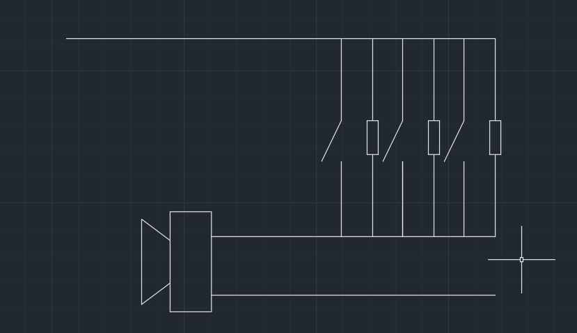
probably something more like this.

1638625551680.png


Or other configs. you can wire them up in different series/parallel configs.

In your diagram, when you turn off all of the switches, the driver wouldn't be connected to the signal source.
 
Dec 4, 2021 at 1:09 PM Post #13,533 of 15,989
@mattmatt damm man you took away my client
Also... What do you guys think of inductor as crossovers
I had tried to simulate inductances but the values are too huge for CMS, an example to make a DD fall, would have to go further than 1mh, the RC cells are less greedy and do the work as well I think.
I know that JH uses some of them in CMS, certainly on second-order filters on medium or high where the values usually remain much lower in//, but honestly I wouldn’t use them
 
Dec 4, 2021 at 2:28 PM Post #13,535 of 15,989
Whats the value in using dip switches?
Switching over crossover points and sorts like that.

I created something back then with 4 tunings in 1 IEM. Can't actually remember. It was a special project for someone. It can be switched to a single BA, to Dual BA and Triple BA and an alternate tuning for the triple setup iirc.
 
Dec 5, 2021 at 10:01 AM Post #13,540 of 15,989
probably something more like this.

1638625551680.png

Or other configs. you can wire them up in different series/parallel configs.

In your diagram, when you turn off all of the switches, the driver wouldn't be connected to the signal source.

Here you have a simple implementation of a two-position DIP switch but series. Without leaving empty positions too.

Zrzut ekranu 2021-12-5 o 15.50.19.png
 

Users who are viewing this thread

Back
Top