luckypictures
500+ Head-Fier
- Joined
- Sep 7, 2007
- Posts
- 584
- Likes
- 10
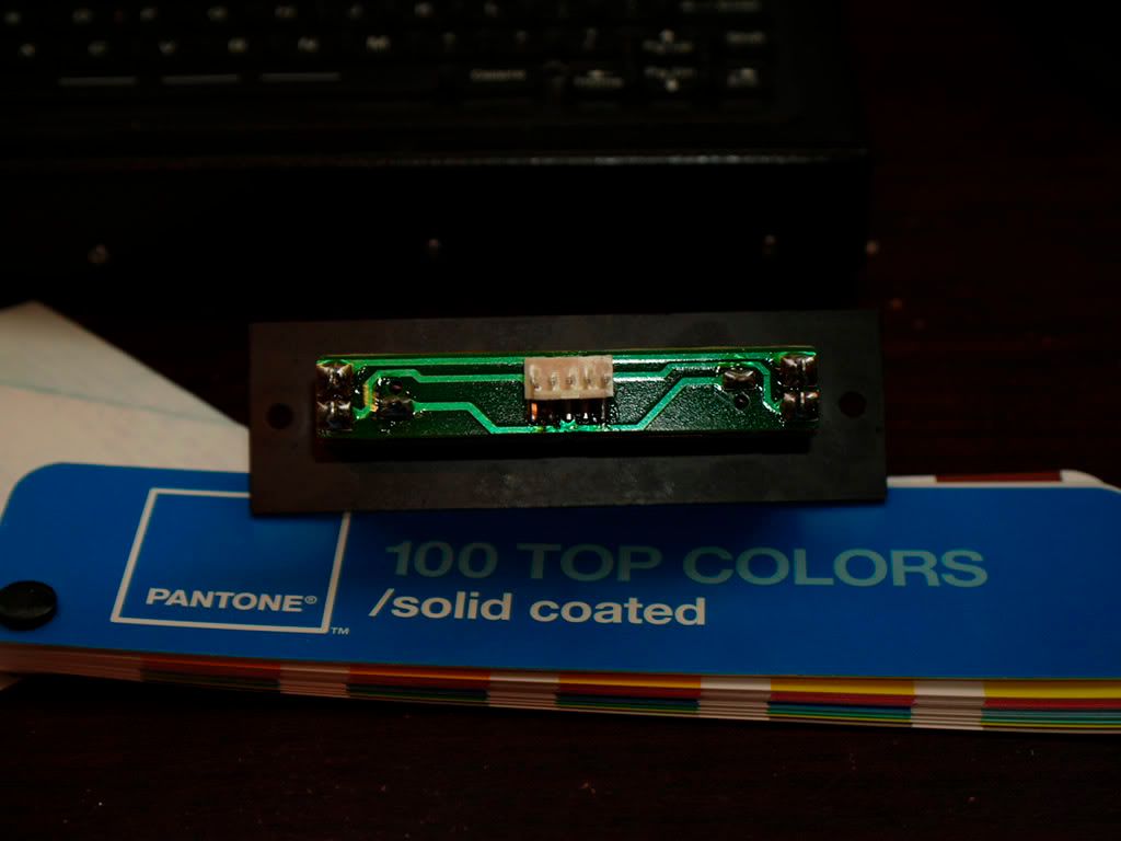
Okay, I got a crossfader, and there's a pinout in the center, and solder tabs at the bottom. I'd like to make a quick and dirty crossfader to feed into my amp. Can anyone tell me what gets soldered where? It's a quick project for an interview I have on monday, hence the ASAP.
What goes where, and where is the output???
Would each source go to either side, then the center is the output, with 2 pins for right channel, two pins for left channel, and a single pin for ground? I can trace on the PCB what goes to which pin, and I would assume that the pins in the center are output.
I tried looking at Alps faders,but none had a similar pin situation.
Thank you in advance!
