cws5
New Head-Fier
- Joined
- Jan 14, 2005
- Posts
- 47
- Likes
- 0
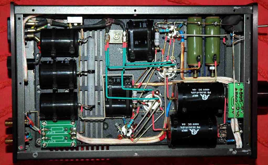
I've begun to try to better understand the circuits in my amps. I've had success with the MG Head. It's got two plate-follower stages that look much like those you'll find described at the various tube info sites on the web. But the Darkvoice 332 is not so easy to figure out. I'm working now on just the power stage.
Here's a description of the circuit (only one channel), which is some kind of cathode follower: the driver stage 6AK5's screen grid (it's a pentode run in pentode mode) feeds the power stage triode's grid. There's no resistor on that grid. B+ hits the plate. The signal comes off the cathode, then splits in two, each line hitting a cap. There is no resistor between the cathode and either of those caps (unlike most cathode follower circuits I've seen on the web. One cap's signal is the positive AC signal, and it's wired to one of the phone jack pins. The other cap sends the AC signal to ground, with that ground wired up to the phones jack ground, plus a 10kohm resistor attached from that grounding point to the terminal of the phones jack where that positive AC signal came in.
So I'm mainly trying to understand why, unlike most cathode follower schematics I see, the cathode load resistor is AFTER the cap. What's that cap doing there?
I'm also curious why, unlike most schematics I've seen, there's no resistor preceding the power tube's grid.
I'd be grateful for a little enlightenment here.
")