Headphone & Amp Impedance Questions? Find the answers here!
Nov 14, 2013 at 8:43 PM Post #181 of 524
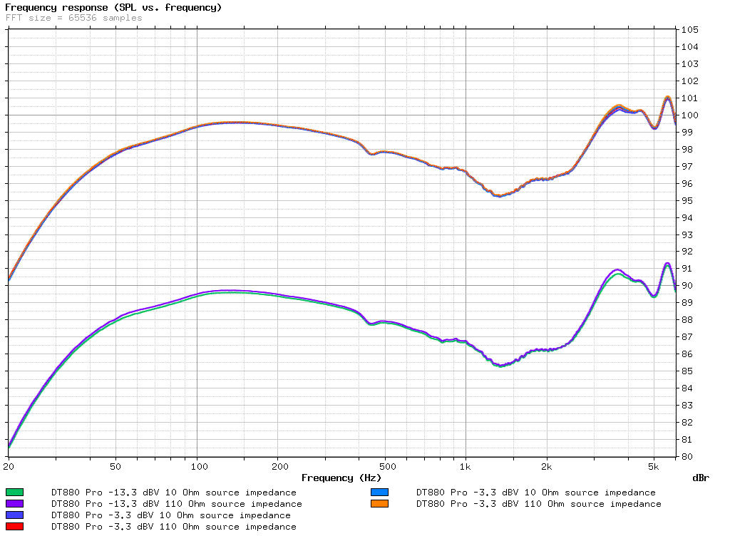
  Perhaps related to this topic, I did some tests on how the output impedance of the amplifier affects the distortion of dynamic headphones. The headphone tested was a DT880 Pro (250 Ω), using sine sweeps at 0.68 and 0.22 Vrms voltage on the drivers at 1 kHz, and with output impedances of 10.3 Ω (Xonar Essence STX headphone output) and ~110 Ω (using 100 Ω serial resistors).
 
Unfortunately, the measurements at low levels contain too much microphone and ambient noise. At the higher level, I repeated the tests twice, to be able to verify the repeatability of the results. The sweeps played were equalized so that the SPL and frequency response are matched at the low and high output impedance. The graphs below assume that 1 Vrms voltage on the driver at 1 kHz produces 100 dB SPL. This is probably not accurate, but the levels on each graph should be consistent nevertheless. Only the right channel was tested.

These are the results I got (click to zoom):
 
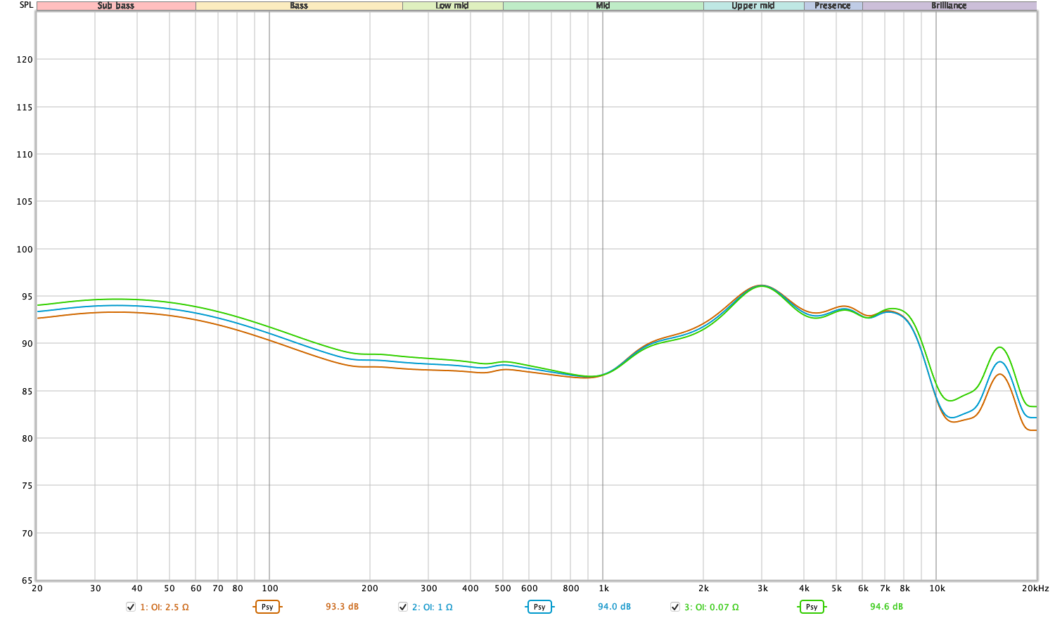
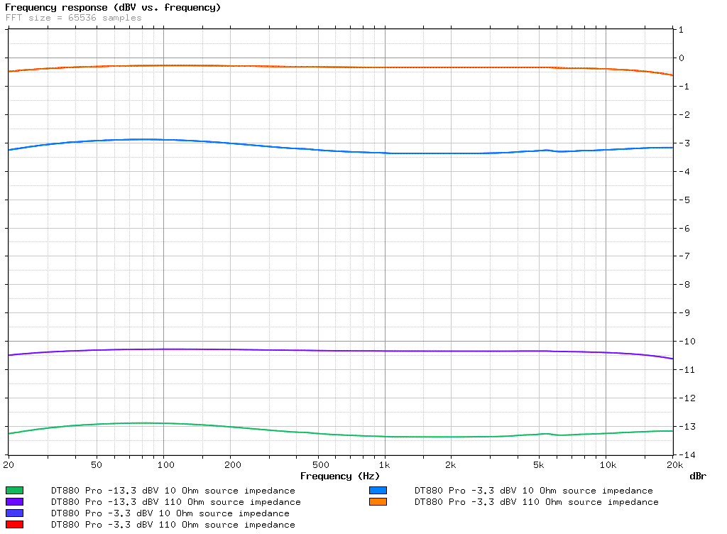
Frequency response: from left to right: microphone, headphone driver, amp output
       
THD vs. frequency: from left to right: microphone, headphone driver, amp output
       
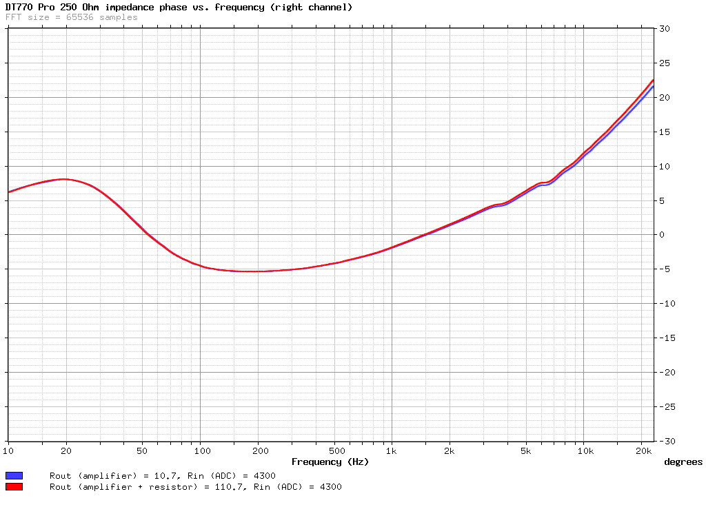
Driver impedance vs. frequency:


Increasing the output impedance of the amplifier does indeed seem to increase the bass distortion of the driver, especially around its resonance frequency. This cannot be explained with the amp "working harder" (see graphs), or the headphone having to produce a higher SPL in the bass range (because it is equalized). The effect is not major, however, it is a difference of about 2 dB, but it is there. With a low impedance source that is equalized to match the frequency response of a high impedance one - which is what I did  - the distortion is lower than it is with actual high output impedance.
 
Although the effect probably varies depending on the headphone model, and some are more affected than others. It would be interesting to try the same with orthodynamic headphones, to confirm if they are not only a more or less purely resistive load, but also fairly linear as well.


Is it possible to generate the THD plots in dBV instead of %?
 
Nov 15, 2013 at 2:06 AM Post #182 of 524
 
By the way, according to these measurements, the E12/Mont Blanc can actually output 6.5-7 Vrms into 150 Ω. The 15.5 Vp-p is specified for 32 Ω, where the measured level was more like 5 Vrms.

 
So ... it can not be calculated this way -> 
 
 
According to E12 specs the 15.5 Vpp max output are 5.5 V.
5.5V into 150 ohms = 200 mW max.

 
?
 
Found out how "5.5V into 150 ohms = 200 mW max." works -> "P = V2/ R" is it right formula ?
 
Than the correct output power would be "72/150=326.6 mW" ? 
 
Also what about max impedance ? Nominal is actually only lowest impedance. 
 
So shouldn't we calculate with max impedance ?
 

This graph shows 370ohm@120Hz so "72/370=132.4 mW"  would be more correct ?
 
Lastly I think we still got something wrong.
 
Because when I look here - http://www.head-fi.org/t/620082/lake-people-g109-g103-thread
 
There are specs for some amp with different ohms already calculated.
 
Max. output level:  
> 18.8 Veff in 600 ohms = 590 mW
> 13.8 Veff in 100 ohms = 1900 mW
> 10.7 Veff in 50 ohms = 2300 mW
> 7.8 Veff in 50 ohms = 1900 mW
> 3.7 Veff in 16 ohms = 410 mW
 
Veff should equal Vp-p if I didn't get it wrong and when I do calculations nearest number I got was 540mW but no luck with 590 
redface.gif

 
When used formula "V=Vp-p/2.8284" and "P=V2/R" I end up absolutely off.
 
Nov 15, 2013 at 2:56 AM Post #183 of 524
Two things;
Pavg = Average power, calculated using Vrms
Pp-p = Max possible power,  calculated using Vp-p.
 
In the lake people specs, V-effective means Vrms.
 
Most of the times, Vrms is the unit used in AC specs.
 
Nov 15, 2013 at 4:32 AM Post #184 of 524
  Two things;
Pavg = Average power, calculated using Vrms
Pp-p = Max possible power,  calculated using Vp-p.
 
In the lake people specs, V-effective means Vrms.
 
Most of the times, Vrms is the unit used in AC specs.

 
Ah, now it works "18.82/600=590"
 
Nov 15, 2013 at 6:03 AM Post #185 of 524
  Is it possible to generate the THD plots in dBV instead of %?

 
Yes. I used % because I thought it is a more familiar distortion unit for most people. I still have the recorded WAV files, though, so I can generate more graphs (including separate D2 and D3) if needed.
 
Nov 15, 2013 at 6:10 AM Post #186 of 524
Originally Posted by Flisker /img/forum/go_quote.gif
 
This graph shows 370ohm@120Hz so "72/370=132.4 mW"  would be more correct ?

 
You should generally use the nominal impedance, since that is approximately the impedance at 1 kHz, and the sensitivity of the headphones is typically also specified at 1 kHz. An amplifier with very low output impedance is basically a voltage source (as long as it can supply the required current), so it does not need to output a higher voltage at 120 Hz than at 1 kHz, otherwise it would not have a flat frequency response. You can view the increased impedance at 120 Hz as increased efficiency, due to the fact that the driver resonates at that frequency (requiring less power to produce the same SPL).

 
Nov 15, 2013 at 11:58 AM Post #187 of 524
   
Yes. I used % because I thought it is a more familiar distortion unit for most people. I still have the recorded WAV files, though, so I can generate more graphs (including separate D2 and D3) if needed.

 
Makes sense. It's just a thought.
 
The reason I asked is because I think % is relative to fundamental. For the headphone and microphone measurements, the fundamentals with the different series resistors have the same level, so % distortion are directly comparable. For the amp out measurement however, the fundamentals have different levels.
 
It might also be helpful to see all plots in dBV to compare distortion of headphone driver and amp out relative to a reference voltage instead of the different fundamentals.
 
Nov 30, 2013 at 12:16 AM Post #188 of 524
My head wants to explode reading the stuff here. So if you don't mind I'll ask a question directly. Is the fiio e11 amp a good enough match with the grado sr80i? my source is sansa fuze+. I'm on a tight budget for the amp so the fiio e11 is all i can afford to get if ever. Thank you.
 
Nov 30, 2013 at 1:58 AM Post #189 of 524
Hi sound science,

I've been trying to get my head around damping. So i decided to make a spreadsheet to tell me how much source resistance increases the reverberation decay time of a signal at system resonance. I used a closed box model (is this ok for open headphones?) to get the Qtc of a system with and without source resistance. I estimated T-S parameters based on plots from inner fidelity, I know thats not very accurate but I was looking for ballpark figures for Qms and Qes. What I found so far was that using a dampening factor of 8 would increase the decay time by a few percent. I'm yet to convert the decay time to reference a more usable measure like a drop in db. Here's the spreadsheet if anyone wants to correct/look/play. Blue fields are inputs.

Neug
 
Nov 30, 2013 at 11:41 AM Post #190 of 524
Hello, Neug.

First, the word you should be using is "damping," not "dampening." Damping refers to the control of the speaker's resonance which is what you're talking about here. Dampening refers to the absorption of sound inside the enclosure. For example, you would call the fiberglass or poly fill stuffing inside a speaker enclosure "dampening material."

Second, I'm not sure just what decay you're talking about. You use -60dB as reference, which to me sounds like you're talking about reverberation decay, i.e. RT60 which is used to describe the reverberation time within an acoustic space. Is that what you're referring to or something else?

se
 
Nov 30, 2013 at 2:57 PM Post #191 of 524
Hello, Neug.

First, the word you should be using is "damping," not "dampening." Damping refers to the control of the speaker's resonance which is what you're talking about here. Dampening refers to the absorption of sound inside the enclosure. For example, you would call the fiberglass or poly fill stuffing inside a speaker enclosure "dampening material."

Second, I'm not sure just what decay you're talking about. You use -60dB as reference, which to me sounds like you're talking about reverberation decay, i.e. RT60 which is used to describe the reverberation time within an acoustic space. Is that what you're referring to or something else?

se


Thanks for the corrections. Post edited. I'm not familiar with a lot of the terms of acoustics. Yes it's reverberation decay, exactly (mathematically).

Neug
 
Nov 30, 2013 at 4:04 PM Post #192 of 524
Thanks for the corrections. Post edited. I'm not familiar with a lot of the terms of acoustics. Yes it's reverberation decay, exactly (mathematically).


So you're trying to figure out the reverberation decay of a pair of headphones? Presumably while they're being worn? I'm afraid that's not making any sense to me seeing as the acoustic space between the drivers and the wearer's head is incredibly small. Nor do I see how the speaker's Qtc would have any effect whatsoever on the RT60 of an acoustic space. That's a function of the acoustic space, not the driver or loudspeaker. Where did the RT60 figures in your spreadsheet come from?

se
 
Nov 30, 2013 at 4:26 PM Post #193 of 524
I'm calculating 2.2*Qtc/fc. The speaker in a closed box has a Q and resonant frequency so it should have a decay time. Maybe reverberation time is the wrong word.
 
Cheers
             Neug
 

Users who are viewing this thread

Back
Top