Gamma-2 (γ2) DAC Thread
Jan 7, 2010 at 3:29 PM Post #1,201 of 2,154
Quote:

Originally Posted by linuxworks /img/forum/go_quote.gif
tried the power cycle a few times on mine. no dice. reflowed solder joints and still nothing. tapped into the line-out pins on the dac and still nothing.


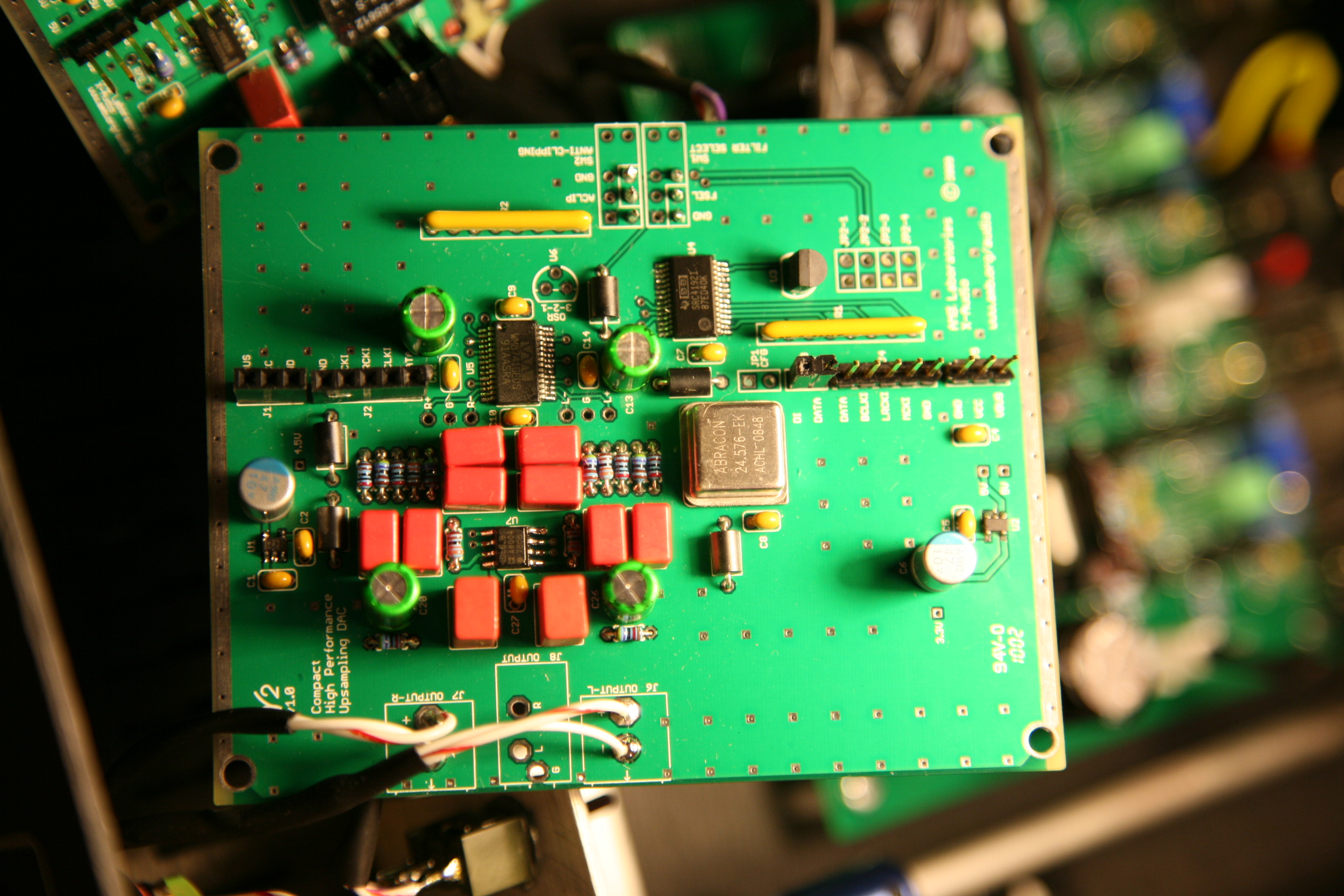
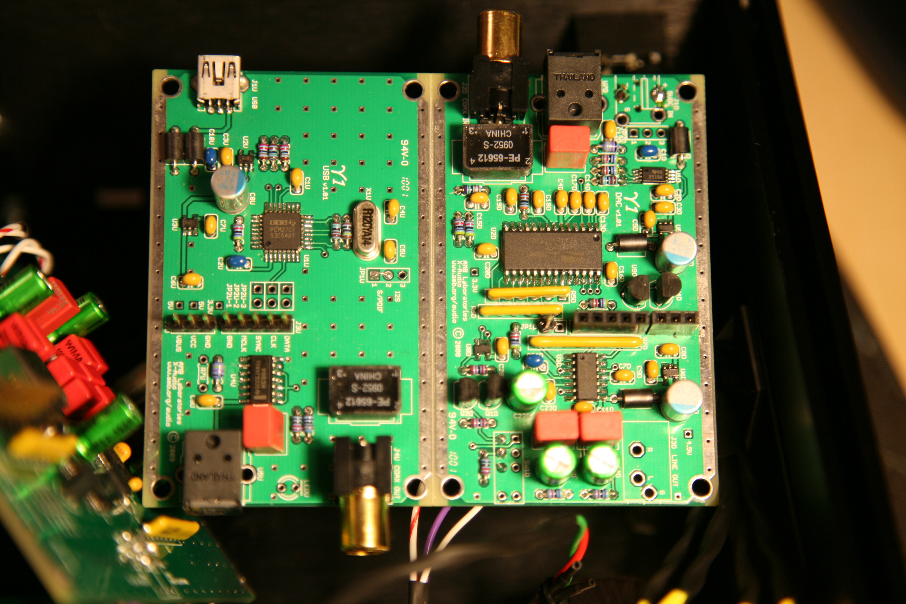
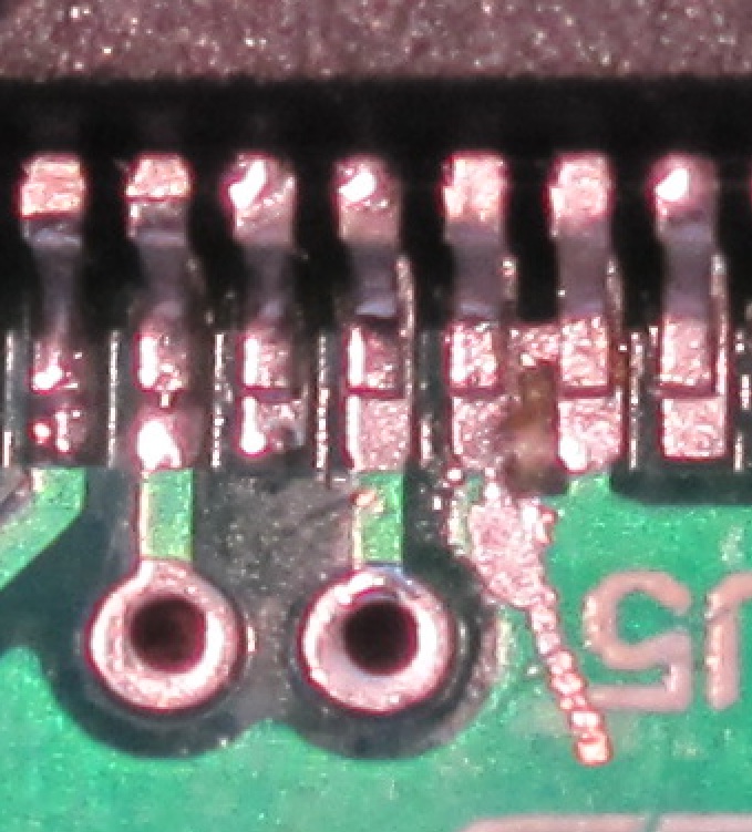
I wonder whether the WM874* are a bit more sensitive as well. Its a pretty complicated chip, and for some reason was a LOT more difficult for me to solder than the PCM2707.
 
Jan 7, 2010 at 3:36 PM Post #1,202 of 2,154
just to keep things really simple (for now) I've decided my 2nd build will not have the SRC chip onboard. one less thing to fail or worry about or debug later.

what I DO want to have is a 2nd board JUST for the src. that way its truly defeatable. too bad the current design did not allow true defeating of the src, that would have been a lot of fun to play around with
wink.gif


what I'm thinking about is using an existing src board (one from the ebay/hk upsampling dac kit) and then just tapping into the 5 lines and giving it pwr/gnd. once the y1 deocodes to i2s, you can use some other board that has the SRC to upconvert, THEN feed that output (as if it came natively from the y1) to the y2. I think that should work as long as I keep the cabling 'exact'.

then, if my src fails, I can truly remove it. not that I assume it will fail but I do like keeping things modular whenever possible.
 
Jan 7, 2010 at 6:23 PM Post #1,203 of 2,154
Quote:

Originally Posted by tacitapproval /img/forum/go_quote.gif
Current draw is 20.2mV without music and 21mV with. This is low, no?

U1 is 4.98v going in, and .29v out and .93v on the NR. U2 is 4.98v in, 1.7v out and .98 on NR. Does this reveal anything?


Mister X (or others) can you tell me if these numbers show anything? I am not quite sure how to interpret them for my problem.
 
Jan 7, 2010 at 6:50 PM Post #1,204 of 2,154
I would just simply replace both regs as a matter of course. sounds like stuff goes in but nothing much comes out. replace them and then retest.

alternately, if you happen to have a variable voltage supply around, you COULD inject that proper voltage to the output of the vreg in question (once you unsolder it).

at least they're easy enough to unsolder and just try new ones. I'd do that.
 
Jan 7, 2010 at 7:03 PM Post #1,205 of 2,154
Hi to everyone, my first post here.

Just ordered gamma 1 and 2 a few days ago.
I read most of the posts, but havent found a reference if anyone used wm8740 instead of wm8741/2. Ive got 2 of 8740 lying around so i thought if anyone compared those two chips? 8740 has a bit lower distortion while 8741 has a bit higher S/N.
 
Jan 7, 2010 at 7:07 PM Post #1,206 of 2,154
I have not tried 'last years chip' (the odd one out; the $5 chip version) but I have tried both of the 41/42 chips. I can't tell them apart. the s/n is only a few db apart and even that sounds questionable to me (perhaps its just marketing). looking at the data sheets, there seems to be no diff. every word and paragraph other than a few db numbers are identical. beats me, what the diff is!

you'd also have to have some serious test gear to be able to actually see any diff between those 2 top end chips.
 
Jan 7, 2010 at 7:38 PM Post #1,207 of 2,154
8740 are used in cambridge audio CD players, in dual differential configuration mostly.
I bought them 2 years ago but had no opportunity to use them till now. Dont know if the digital filter features on 8741/2 are worth it to get new chips instead of old. Thats why i thought of checking out first.
 
Jan 7, 2010 at 8:22 PM Post #1,208 of 2,154
Quote:

Originally Posted by OliverK /img/forum/go_quote.gif
Dont know if the digital filter features on 8741/2 are worth it to get new chips instead of old. Thats why i thought of checking out first.


In my opinion, no. If I built another G2 I would leave the anti clipping and filters off as well as the G1 output and digital outputs on the front panel leaving only the input selector.
 
Jan 7, 2010 at 9:24 PM Post #1,210 of 2,154
I concur. I think the y2 would look much cleaner with less clutter in the front of the unit. I'm debating the usefulness of the front mini-jack also. Does anyone use it?

Not to thread jack, but does anyone have panels for the y2 without the switches or the front coax and toslink outputs? Or just an extra set of AMB front and rear panels I can take off your hands?
 
Jan 8, 2010 at 1:31 AM Post #1,212 of 2,154
Quote:

Originally Posted by francisdemarte /img/forum/go_quote.gif
Not to thread jack, but does anyone have panels for the y2 without the switches or the front coax and toslink outputs?


I don't have 'panels' but I did make an alternate chassis for it:

4254836115_95191d12b3.jpg


http://www.head-fi.org/forums/f6/pos...ml#post6295441
 
Jan 8, 2010 at 3:39 AM Post #1,213 of 2,154
It was the ldo's. With new ones in she is singing again!
Thanks everyone.

Edit: It was working fine for a few minutes. Now the regs are gone again. Maybe it wasn't a dmm probe that caused this, after all. Thoughts?

Edit Two: I think I found the problem. Shoddy wiring on my part, suprise, suprise. Unfortunately, I need to order more regs to test my hypothesis.
 
Jan 8, 2010 at 4:43 PM Post #1,214 of 2,154
Quote:

Originally Posted by linuxworks /img/forum/go_quote.gif
I don't have 'panels' but I did make an alternate chassis for it:

4254836115_95191d12b3.jpg


http://www.head-fi.org/forums/f6/pos...ml#post6295441


That's an amazing build! What enclosure is that and what are the extra resisters/caps on the RCA's?
 
Jan 8, 2010 at 4:49 PM Post #1,215 of 2,154
Quote:

Originally Posted by francisdemarte /img/forum/go_quote.gif
That's an amazing build! What enclosure is that and what are the extra resisters on the RCA's?


thanks
wink.gif


on the 2 rca jacks in the back, those are coax-in ports. the standard config that I use is:

port - .01uf cap - pulse_trafo - 75ohm R in parallel

4254837463_ec116ba943_o.jpg


if you look close you can see blue caps on the center lead. that goes to the trafo and the rca ground goes to the other input leg of the trafo. 75ohm R's are soldered to the secondary and that is supposed to give a nice 75ohm 'view' into the rest of the downstream circuit. from there it goes to a differential rs422 receiver chip. that chip receives the trafo 'data' and TTL'izes it so that it can be sent to the analog mux switch chip.
 

Users who are viewing this thread

Back
Top