One of the prototype team members won't be able to build his γ2 due to a new job and work/family priorities, so he is looking to pass on his γ2 and γ1 boards, plus a few other parts to someone who would be a worthy prototyper. If you're interested, PM me and I'll put you in touch with him.
Originally Posted by amc /img/forum/go_quote.gif oh man, every day I hope for that notice that my box of boards and parts is at the post office, but it has yet to clear customs and arrive. I cant wait! Great pictures everyone.
Good o'l Canada Post.. Slower than the mail to Australia and Europe.. glad I'm not the only one waiting for the gamma2 board.. My one consolation is that I'm sitting in a lovely cottage by the sea for the next 5 days.. I did bring my "kit" in case it's rainy, but so far there seems to be no evidence of that on the horizon...
If I jumper JP2D pins 2 and 3 to straight wire usb power, would that let me know if my TPS2115 is bad even if it's still soldered to the board?
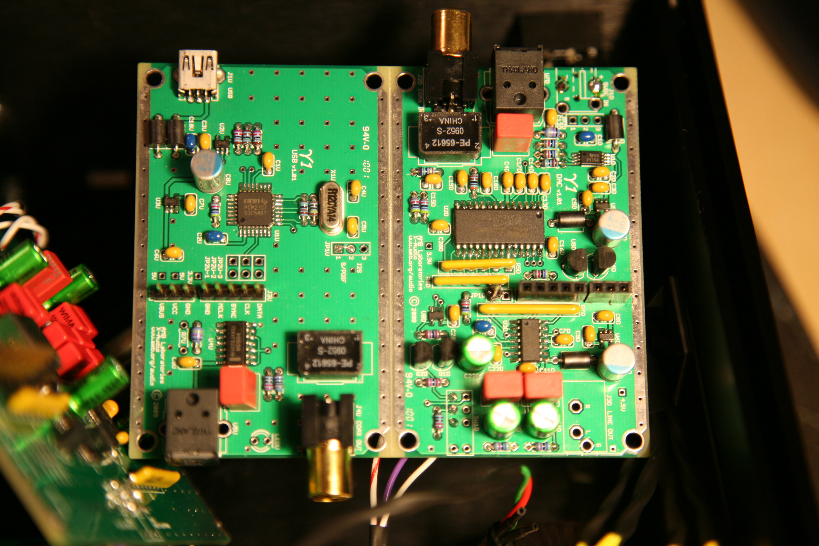
Reason I ask is I have 5V on VBUS with the boards apart, and 4.95V when I plug the two together, but all other test points measure appox. 2.4 or 2.5V when plugged together, including VCC. I pass the y1 usb board initial check steps 1, 2, and 3, with the computer recognizing the dac. I also checked R4U to make sure it was 47k. No cold joints on any regulator on either board, verified with ohmmeter.
I went ahead and jumpered it anyway, and now my 3.3's are 3.28, so good there.
VBUS is 4.75, VCC is 4.73. Led switch changes from red to green when playing a song in iTunes. No sound. I am tired, so I will give it a go tomorrow.
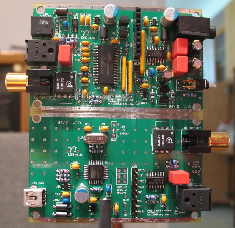
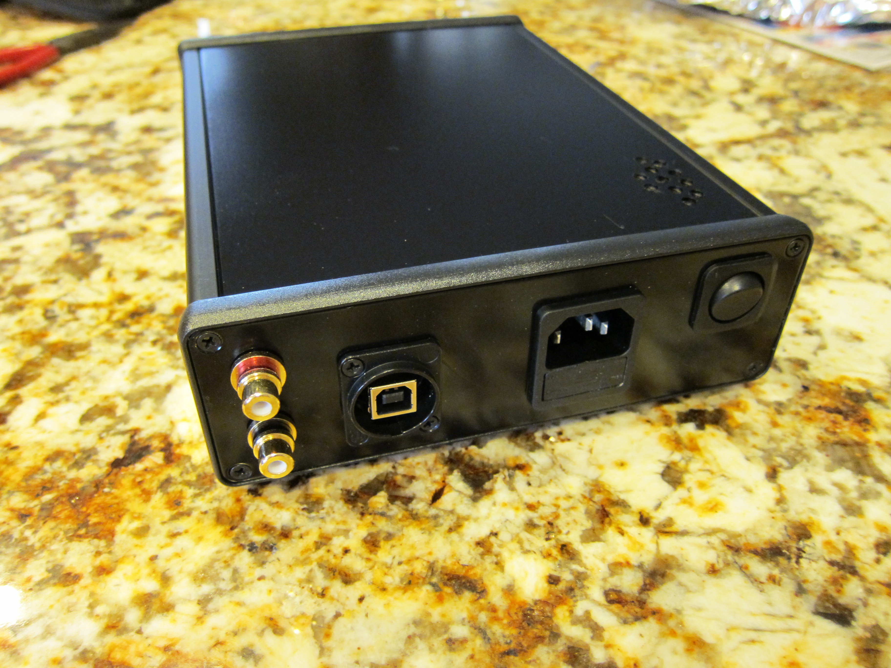
A few parts are missing, the coax rcas and optical transmitter, external power jack, rca and mini on the y1.
The third pic shows the I2S pin missing, but it's in the pics above it.
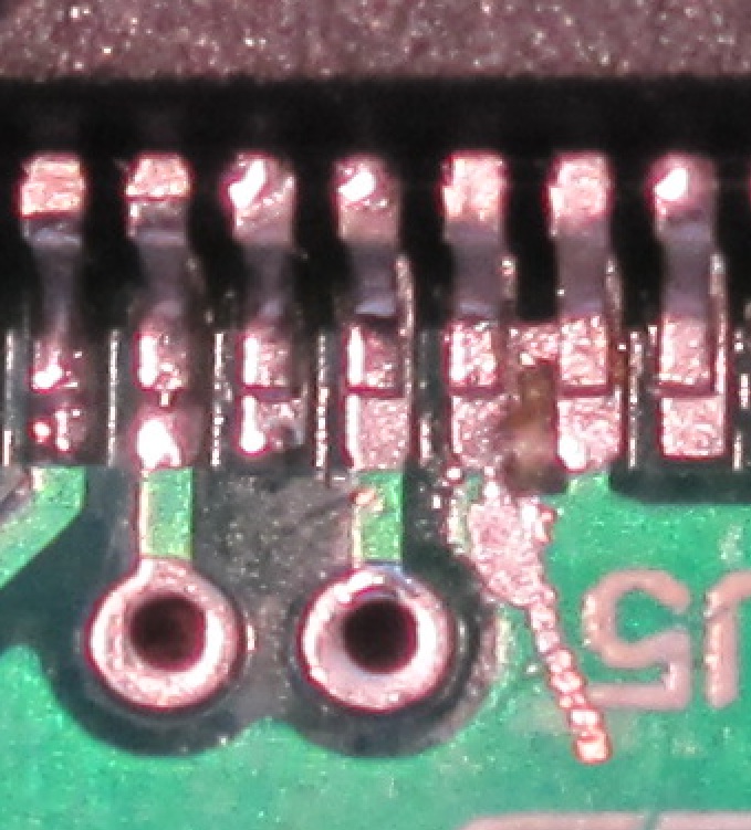
Your symptoms suggest a marginal short somewhere (jumpering JPD2 effectively removed the current limiting feature of U1D so it's no surprise that the VBUS voltage increased).
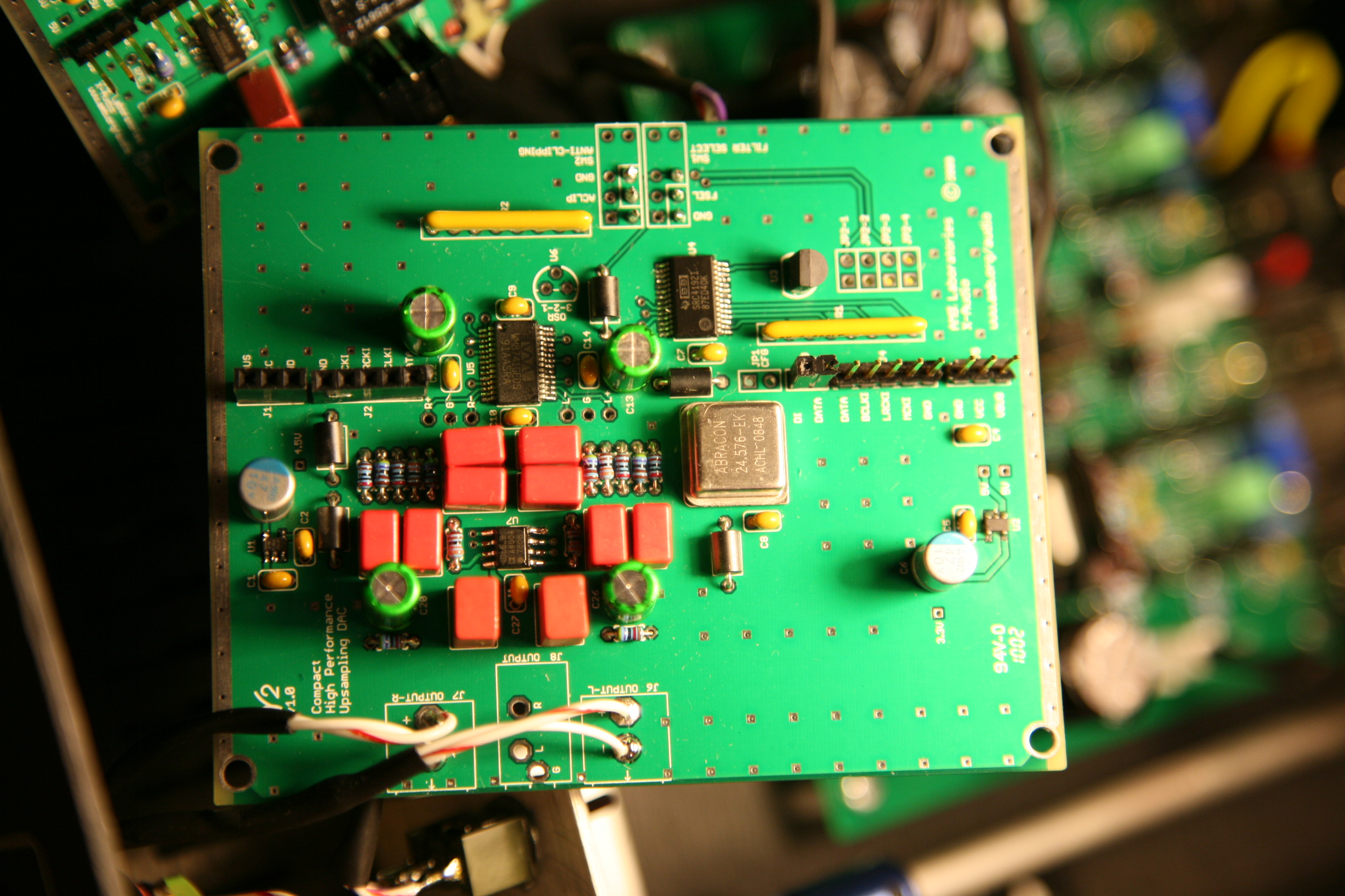
Try cleaning up that big blob of solder on the supply pin of X1 and see if helps matters any.
Originally Posted by MisterX /img/forum/go_quote.gif Your symptoms suggest a marginal short somewhere (jumpering JPD2 effectively removed the current limiting feature of U1D so it's no surprise that the VBUS voltage increased).
Try cleaning up that big blob of solder on the supply pin of X1 and see if helps matters any.
Thanks, I will try that as soon as I get home. I will figure it out today, I just thought I would post some pics and see if someone noticed something obvoius right off the bat. I think I spent a little too much time on some of the regulator pins maybe, trying to get the joints to look good. And obviously I overlooked some other stuff as you pointed out.
Originally Posted by TeraHz /img/forum/go_quote.gif BTW I didn't know we can have two active signals running like: usb -> opto out, and opto in -> 3.5mm out.
Yeah, the USB to SPDIF converter is always active if populated and connected to a PC.
Originally Posted by Mr.Duck /img/forum/go_quote.gif I'm impressed with your casework, TeraHz. Even more impressed you managed to drill a square hole lol. How did you do it?
Thanks
Square holes are not any harder than round ones that are much larger than the closest (smaller) bit I have. I just drill small holes around the inner edge of the square and then hammer out the center, the rest is just a little work with the file. For some reason I can't figure out a good way to use the Dremel.
This site uses cookies to help personalise content, tailor your experience and to keep you logged in if you register.
By continuing to use this site, you are consenting to our use of cookies.