I would just like to say that I am watching/subsrcibed to this thread and only havent said anythign because I have no idea what to say in this situation. I'm not quite at that level yet heheh.
@jdkJake... I don't think reflowing will solve the issue. Nor will posting pics. This was a working Y2 for the past year or so. Just to reiterate - I shorted out a metal knob and metal 1/8" connector, which in turn was connected to and subsequently zapped my Gamma 2 with probably way more voltage than what U7 or U5 can handle. This is just a guess. The one anomaly is more voltage being fed to C26, which should be getting around 2.2v.
I'm going to post to ambs forum, but usually come here first. This is my DIY home.
I'm assuming it's easiest to check this by using the vias on the the bottom of the board for those respective positions. What voltage reading should be normal? ~2.2v?
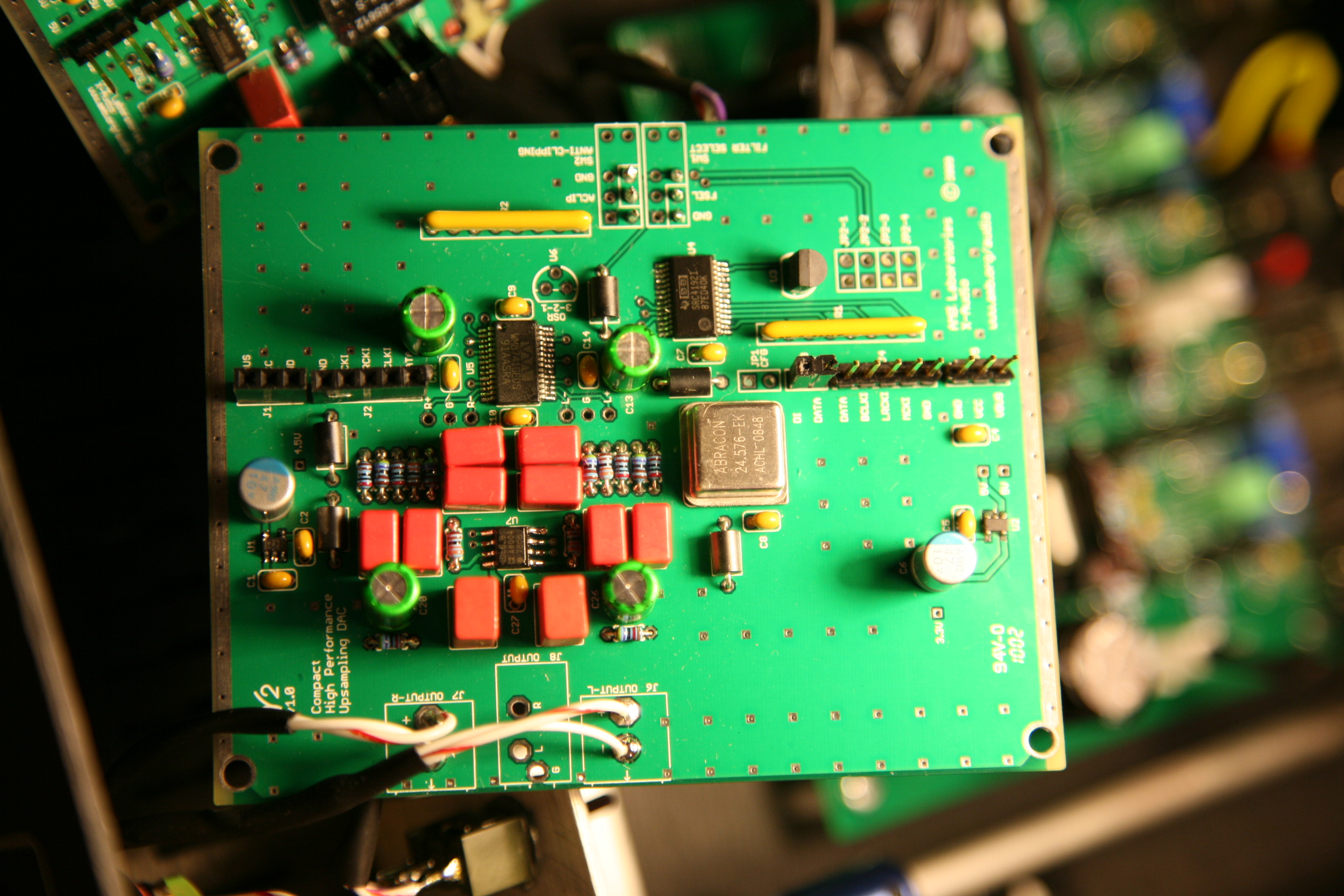
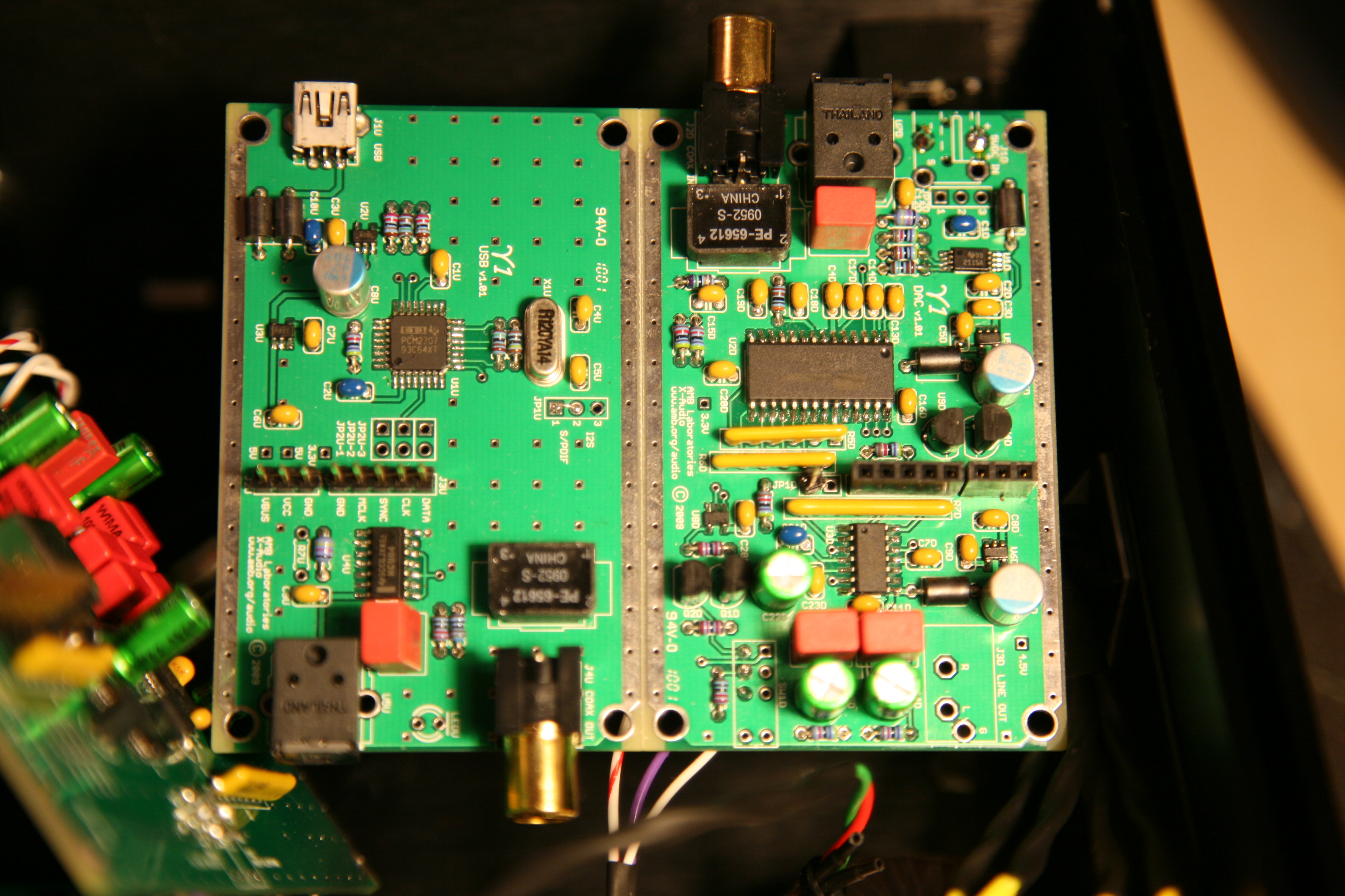
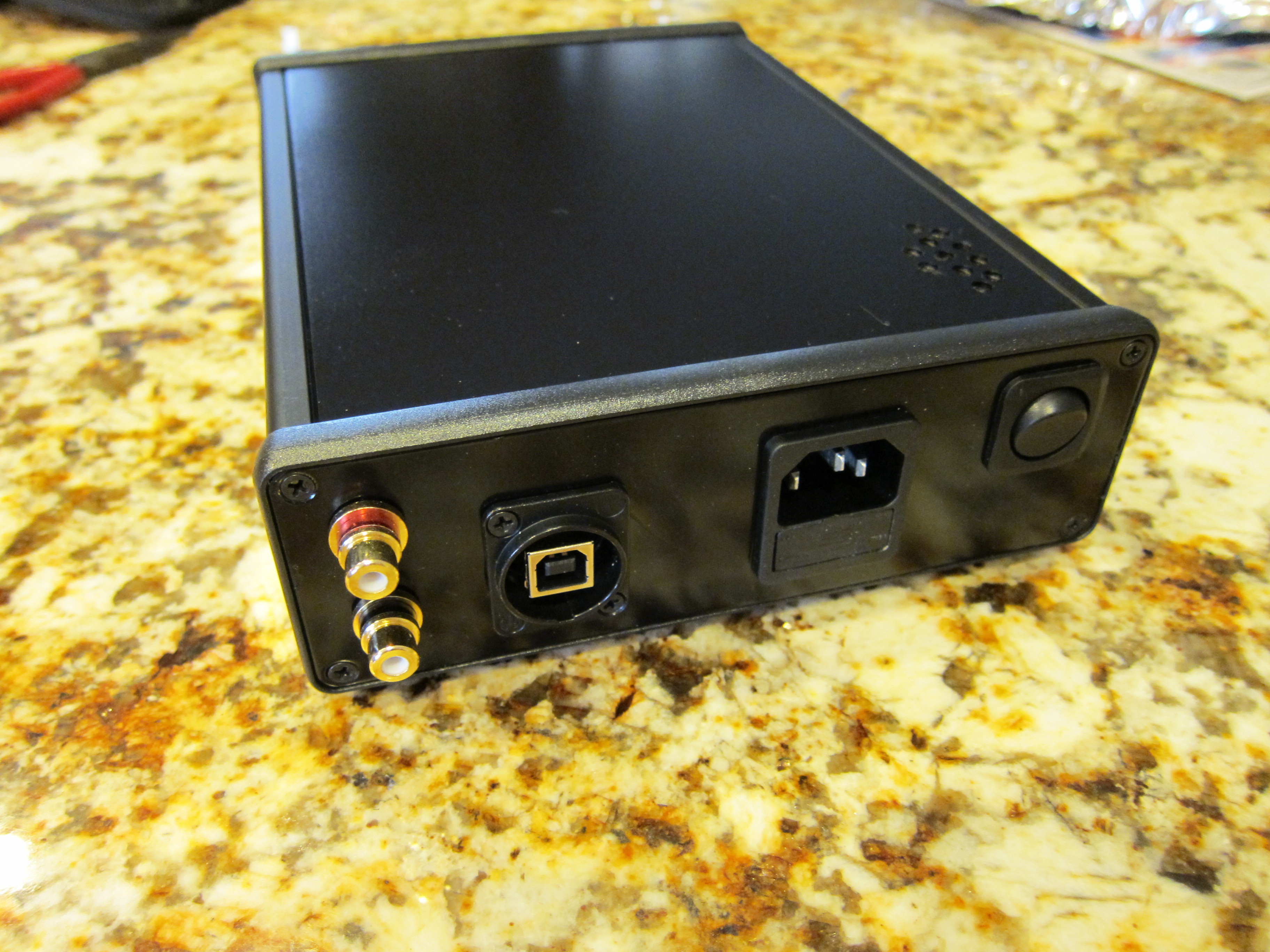
So to complete the proverbial circuit here's an update with my fried Gamma 2:
Measured VMIDL and VMIDR and got close the 2.3v readings. Then measured Pins 1/3 and 5/7 and got the 3.5v readings on 1 and 3. 5 and 7 measured just fine. I still got 4.5v readings at C26.
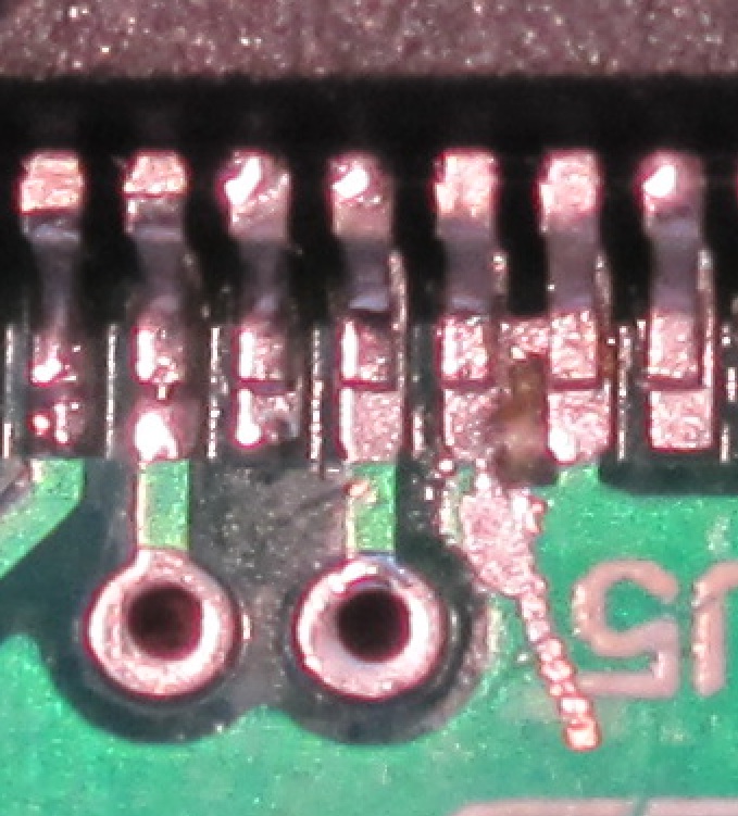
I proceeded to order a new U7 and U5 (just in case) and pulled out some of the box caps around U7. Then using some chip quik I pulled U7 and put the new one in. Then I put back the box caps I pulled. Fired the puppy up and took some measurements via USB from both a Mac Pro and MacBook Pro...
Mac Pro
VMIDL 2.326
VMIDR 2.315
pin1 2.327
pin3 2.312
pin5 2.298
pin7 2.273
MacBook Pro
VMIDL 2.264
VMIDR 2.254
pin1 2.270
pin3 2.253
pin5 2.241
pin7 2.216
Finally, I plugged in my CTH and some phones and Voila! Everything works again!
I've got an extra U5 (WM8471) now if anyone needs it.
What did you think of using chip-quik? I had to temporarily remove the crystal oscillator from mine (long story) and used a precision tip heat gun with the part surrounded by a cooper tape cone. It worked well, but that was only four pins. Not sure how it would work for the multi pin chips.
I see where Fry's carries chip-quik, so, I might pick some up to have on hand.
Chip Quik really works for SMDs, but helps with through hole devices as well. It's definitely worth having on hand. I'd imagine it would be helpful with the receptacles and pin headers if they needed to be pulled. Otherwise, I'd think they'd be near impossible to pull.
I'd say it's still pretty damn good. Another alternative that gives way less features in terms of I/O, but is still really good none-the-less is the PupDAC. I'm also going to be building the Subbu v3 DAC, which is based off the ESS Sabre 9023.
I think I want to add balanced output to my Gamma2, few questions:
1) I should just tap the Balanced outputs of the chip, add some caps, and then it should be good?
2) The normal outputs would function fine if I didn't use the XLR's, correct?
I am adding them through holes in the case where i'll string the wires through. So I can just tap VOUTLP/N and VOUTRP/N, add a capacitor or 2, and then ill be good to go? Got any recomendations as to what series of caps and resitors I should use?
This site uses cookies to help personalise content, tailor your experience and to keep you logged in if you register.
By continuing to use this site, you are consenting to our use of cookies.