Gamma-2 (γ2) DAC Thread

Aug 8, 2010 at 7:10 AM Post #1,951 of 2,154
How many of these parts do I need to build a full gamma1 , full++   (i've not decided which one yet) and gamma2 ?
 
Gamma1:
 
JP1D, JP2U-1, JP2U-2, JP2U-3
 
  [size=smaller]2P short pin header[/size] [size=smaller]517-647-01-36 (break apart)[/size]
 
JP1U, JP2D
 
[size=smaller]3P short pin header[/size] [size=smaller]517-647-01-36 (break apart)[/size]
 
-
 
  [size=smaller]2P jumper shunts[/size] [size=smaller]649-68786-202LF (single)[/size]
 
 
Gamma2:
 
 
J3
 
[size=smaller]2P pin receptacle[/size] [size=smaller]517-850-01-08 (break apart)[/size]
 
JP2
 
[size=smaller]2-row 4P short pin header[/size] [size=smaller]649-67997-108HLF[/size]
 
 
If I go with the full ++ route and later upgrade to gamma2, then I have to desolder the ribbon cable which provides connectivity between the USB and DAC modules?
 
Aug 8, 2010 at 2:02 PM Post #1,952 of 2,154


Quote:
How many of these parts do I need to build a full gamma1 , full++   (i've not decided which one yet) and gamma2 ?

 
Have you looked at the parts lists and notes at both the γ1 and γ2 websites?  Your answers are all there.
 
Quote:
If I go with the full ++ route and later upgrade to gamma2, then I have to desolder the ribbon cable which provides connectivity between the USB and DAC modules?

 
Yes.
 
Aug 11, 2010 at 2:30 AM Post #1,953 of 2,154
Update on Gamma2 case, I did the front and rear panels today. Front Panel is glued to the case and the rear panel is removable. It holds in place like a few portable amps, a threaded rod fixed to the case with thumb nuts holding it together. Case was sanded with a belt sander and I noticed that the top panel was slightly convex in the middle, hence the white bitumen in the middle. A few other recessions where also taken care of. Overall I'm quite pleased with the result taking into account that I'm using old spares of wood. Next week I'll be veneering the case.
 
Front Panel with holes for the Gamma2 Switches.


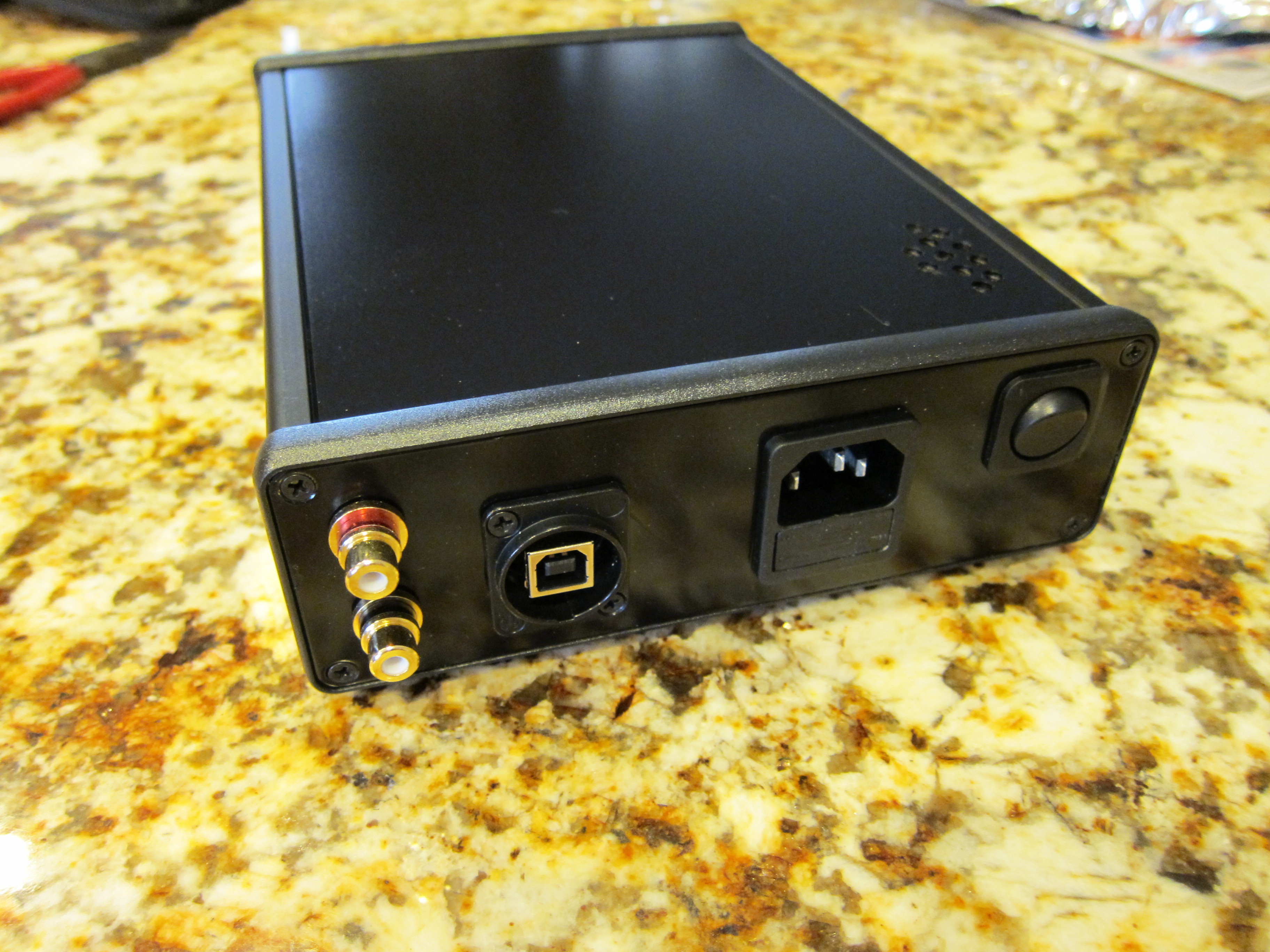
Top and back panel, I opted to make a large rectangular opening on the back instead of drilling the individual holes for each connector as this proved much easier and faster, andwill make veneering much easier too. Still some sanding to do on the inside corners .


Detail of the inside of the side panel. The top rail is slightly deeper because of the wider gamma1 pcb.


Back panel removed, you can see the treaded rod assembly, will be glued with epoxy after the veneer is done.


Back with the Gamma2 inside, there is good clearance around each connector and I'm satisfied with the result.


Front with Gamma2, the left top hole isn't perfectly centered around the switch, but I'll grind it better, the veneer will also correct this.

 
Aug 14, 2010 at 3:02 PM Post #1,954 of 2,154
guy,i bought some parts from the only electronic store in my country but i feel that the materials are of bad quality and not like the parts i ordered from Digikey.i am really not sure if it would make any difference.
here are pics


Aug 14, 2010 at 4:19 PM Post #1,956 of 2,154
midoo, those ceramic disc capacitors are awful.  You should use multilayer ceramics as specified in the parts list.  As for the electrolytics, they are probably of questionable quality as well.
 
Aug 14, 2010 at 4:32 PM Post #1,957 of 2,154
ya i knew they were terrible.i tried telling the electrician who brought them to me that these should go to the bin and that they are not multilayer but he argued it wont matter.i will order many parts from digikey tonight and also parts from amb shop.
what a money waste.i will put them in the bin.
 
Aug 28, 2010 at 11:33 PM Post #1,958 of 2,154
Finally finished my y2 build this week (quiet house, warn iron). This is the option D version y1 with corresponding y2:


I had two issues, a soldier bridge on U4 pin 8 and 9, which manifest itself as pin 14 (mute) asserting not ready to pin 15 (as it should!). Thanks to AMB and MisterX for the well placed test points to determine that relatively quickly. The second issue was the ground pin on X1. Even though I hit it a couple of times with the old iron, Still no clock. I pulled the chip and low and behold, the ground pin was clean. Too clean. A wise tech I know always said to tin a gold contact prior to soldering. I did this on my GrubDac, but not on this one. Turns out he was right (as usual) and it works great now. He is still laughing at me.
 
I am going to power it with this beauty:


Now to case it up.
 
I am starting to get the hang of this SMD stuff. Still not a big fan, but, capable nonetheless. 
 
Sep 3, 2010 at 3:09 PM Post #1,959 of 2,154
I got a fresh new PCB and all of the reccomended components, i put it all together it did not pass the initial check, then i just reflowed EVERY SINGLE JOINT (there were no visible bridges or cold joints) and it still does not pass the initial check, this is the second board i have gone though i have no idea what i am doing wrong
 
I omitted U4 and all the components the note tells you to omit, i also used a WM8741 so i omitted U6 as it says, i jumpered all the JP2 slots.
 
then i just rechecked it and the same problem, it does not pass the initial check. Here are my testing results (multimeter set at 2000k ohms)
 
4.5V: 072
3.3V: 000
5V(top): starts around 750 and slowly climbs till it evens out at about 930
5V(bottom): infinite (so it checks out)
 
it is clear that the 3.3 has a break in the circuit somewhere (if i am not mistaken)
 
but i have no idea what is wrong with the others, also its weird because if i switch up the leads then i get a negative number on 4.5 (-025)
 
also i just rechecked 4.5 and now it is giving me 024, and still a negative number when i switch it (-006)
 
can someone please help me
 
Sep 3, 2010 at 6:18 PM Post #1,962 of 2,154


Quote:
Can you post some pictures of both boards, top and bottom?


Lots of light and focus please.

BTW, you should be measuring voltage and not resistance.


i am checking for continuity first, because if it has shorts or bridges there is no point in checking voltage until i fix them.

 
Quote:
Continuity checks when the meter is set on a high (2000k ohms) scale are not very useful.
Do you have some pictures?


Oh, my bad, i put it down to 200 (lowest my meter goes)
 
all are infinite except 3.3V
thats around 50  +/-5
 
and i dont have any pictures atm, i will take some tonight
 
 
Sep 3, 2010 at 7:18 PM Post #1,963 of 2,154
Without an X1, L5, C8, U4, L4, C7 and U3 installed the 3.3 volt problem is either with U2 or U5.
Are you sure you have the right part installed in the U2 position and that U5 is installed the right way around?
 

Users who are viewing this thread

Back
Top