Gamma-2 (γ2) DAC Thread

Mar 14, 2010 at 7:51 PM Post #1,667 of 2,154
Quote:

Originally Posted by slowpogo /img/forum/go_quote.gif
J1 VCC/VBUS to Gnd measures 2.90v. JP2D pin 2 to Gnd is 2.69v. Pin 7 of the power muxer (OUT) measures same as 3.3v test point, fluctuating between 2.95-2.99.


Let's measure JP2D's pin 1 and pin 3 with everything plugged in. Also measure your USB board's VBUS. Pin 1 of JP2D (square) measures your TREAD's voltage, and pin 3 measures VBUS, your USB's power. I'm looking for two VBUS measurements because I'm thinking the contacts aren't making proper connection with your boards. If one of the inputs is 2.9V, then it would mean the power section of either your TREAD or your computer is bad.

If you want to use USB power, you can just jumper JP2D accordingly. You won't have to remove the mux, just don't plug in the TREAD. Don't do anything yet until we get new measurements.
 
Mar 14, 2010 at 11:38 PM Post #1,668 of 2,154
Quote:

Originally Posted by ShinyFalcon /img/forum/go_quote.gif
Let's measure JP2D's pin 1 and pin 3 with everything plugged in. Also measure your USB board's VBUS. Pin 1 of JP2D (square) measures your TREAD's voltage, and pin 3 measures VBUS, your USB's power. I'm looking for two VBUS measurements because I'm thinking the contacts aren't making proper connection with your boards. If one of the inputs is 2.9V, then it would mean the power section of either your TREAD or your computer is bad.

If you want to use USB power, you can just jumper JP2D accordingly. You won't have to remove the mux, just don't plug in the TREAD. Don't do anything yet until we get new measurements.


Pin 1 of JP2D: ...is weird. It first measured 4.95v, but then as I was watching, the voltage started slowly going down until about 4.7v - a few seconds later I measured again, and it was dropping rapidly, ending up around 3.7v. I measured again after waiting 5 minutes, and it was back up 4.95v, then started dropping, the same behavior.

But then I waited several minutes, a second time, to see if the behavior repeated, and that time it was still down at 3.7v - it did not jump back to 4.95 like it had previously.

I will mention, however, that when measured directly from the DC plug, the TREAD voltage remained exactly 5.00v, all the time, even as Pin 1 was getting lower.

Pin 3 of JP2D: 5.05v

The 5.0v test pad next to VBUS on the USB board measures the same as Pin 3 above, 5.05v. But the other 5.0v test pad (next to VCC on USB board) - AND the 3.3v test pad above it - BOTH measure 2.4v.
 
Mar 15, 2010 at 12:33 AM Post #1,669 of 2,154
Some more things to measure:
- Measure the voltage before and after the ferrite L4D
- Check resistances of R14-16D
- Make sure all pins of JP2D are not shorted to ground (resistance should be high)

Does your y2 work fine if you use either USB or TREAD only? If not, you can jumper JP2D for USB power only and see if it works. For now, your TREAD is probably not the problem.
 
Mar 15, 2010 at 1:52 AM Post #1,670 of 2,154
Quote:

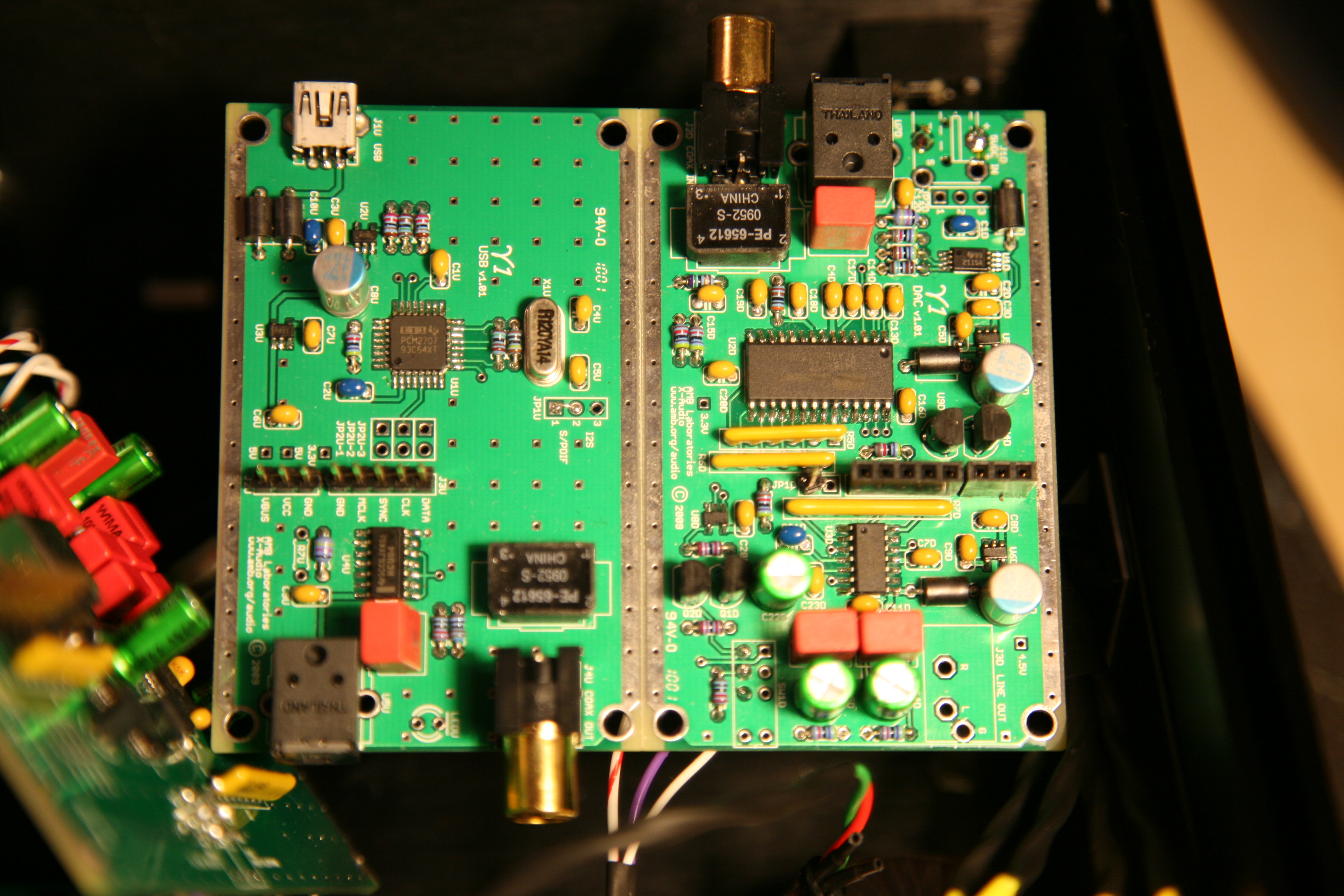
Originally Posted by ShinyFalcon /img/forum/go_quote.gif
Some more things to measure:
- Measure the voltage before and after the ferrite L4D
- Check resistances of R14-16D
- Make sure all pins of JP2D are not shorted to ground (resistance should be high)

Does your y2 work fine if you use either USB or TREAD only? If not, you can jumper JP2D for USB power only and see if it works. For now, your TREAD is probably not the problem.


1. voltage on either side of ferrite is 4.95v
2. R14-16D are color-coded correctly, though when measured in the board they read 23.2k, 23.2k, and 1.2k, respectively.
3. JP2D pad 3 measures high resistance, 1 and 2 measure around 30 ohms

USB plugged in alone: when first connected to USB the source switch turned on green (coax source plugged in), and there was hissing and whining. Then, the switch went to red and there was a constant droning sound.

TREAD plugged in alone: switch turns on red, absolutely no sound at all

When JP2D is jumpered for USB power only, it works perfectly.
 
Mar 15, 2010 at 2:34 AM Post #1,671 of 2,154
Do you have the SPDIF out on the y1 populated? Keep the y1 and y2 separated and powered separately, and connect their opticals or coaxials together. I think you may need to connect USB's VCC And VBUS temporary, but I won't force you to do it.

Did you measure the JP2D measurements while it was on? I wanted unpower measurements, but was the TREAD plugged in at this time?\]

Edit: One thing that bothers me. Since both your TREAD and USB's voltage are so similar, I think it may also be a source of your problem. The mux might be oscillating between DC and USB input. Bring the TREAD's voltage to 5.1V , but no more than 5.5V, remove the jumper at JP2D, and see what happens when you plug them both together at the same time.
 
Mar 15, 2010 at 3:10 AM Post #1,672 of 2,154
Quote:

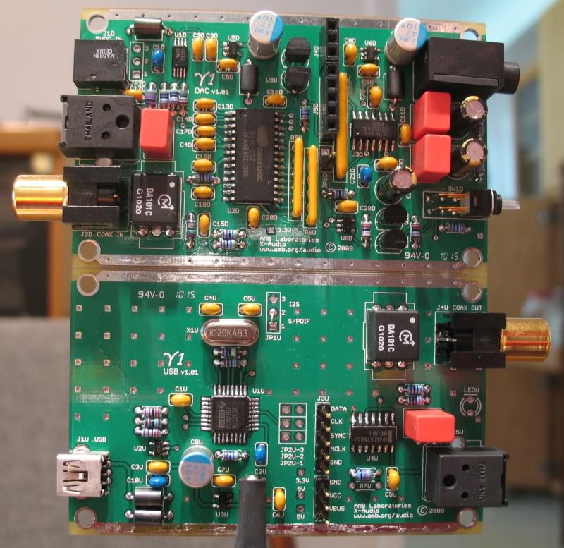
Originally Posted by ShinyFalcon /img/forum/go_quote.gif
Do you have the SPDIF out on the y1 populated? Keep the y1 and y2 separated and powered separately, and connect their opticals or coaxials together. I think you may need to connect USB's VCC And VBUS temporary


Did you mean keep the y1 USB and DAC boards separated and powered separately? I did this, and connected coax out on the USB board to coax in on the DAC, used the y1 3.5mm output - and it works fine. (the y2 was sitting on the other side of the desk for this) The TREAD apparently works great in this scenario.

Quote:

Did you measure the JP2D measurements while it was on? I wanted unpower measurements, but was the TREAD plugged in at this time?


The measurements I gave were unpowered, nothing plugged in.

Quote:

Edit: One thing that bothers me. Since both your TREAD and USB's voltage are so similar, I think it may also be a source of your problem. The mux might be oscillating between DC and USB input. Bring the TREAD's voltage to 5.1V , but no more than 5.5V, remove the jumper at JP2D, and see what happens when you plug them both together at the same time.


I bumped the TREAD power up to 5.25v, then connected everything (y1 + y2, USB and TREAD, coax input). When I first plugged in USB, it gave a warbly analog-synth-sounding drone, switch was red. Then when I turned on the TREAD in addition to this, the switch turned green for about half a second, then went red, and there was a static hiss with some faint whining.

EDIT: Just for giggles I tried jumpering JP2D for external power only, and attached the y2 and used its output. At first it worked perfectly, but after 20 seconds or so it reverted to red switch hissy-fit mode.
 
Mar 15, 2010 at 4:43 AM Post #1,673 of 2,154
The power mux won't oscillate between the two power sources. Preference is given to external power if both are present. The switching threshold has hysteresis to prevent oscillatory behavior.
 
Mar 16, 2010 at 6:28 AM Post #1,674 of 2,154
It looks like maybe ShinyFalcon is only a weekend headfi-er...in the meantime if anyone else has some insight on my build, here is what I can gather:

-although voltages do not measure correctly on either the y1 USB or DAC boards, when they are powered separately and left unbridged, but connected from the USB board coax output to the DAC coax input - y2 not connected - it seems to work fine
-when jumpered for USB power only, the y1+y2 combo works fine

Basically, any time external power is thrown in the mix, things go awry - unless the y1 DAC is kept totally isolated (the first scenario above). The y1 DAC plays with itself just fine, but does not like to play with others. I might guess it is an issue with the bridge pins, but they all show continuity when the boards are connected.

All parts are correct and in the right place - so it seems the only explanation is a damaged part at this point. Especially considering that everything worked fine at first, then problems gradually started appearing, and then failure. I will try to reflow joints another time but they all look good and show continuity..

I would like to be able to use my TREAD, as I did notice a (slight) sound improvement over USB power...
 
Mar 16, 2010 at 6:38 AM Post #1,675 of 2,154
The first thing I'd try is an external power source other than the Tread. Have you got a usb cable you can cut in half/the end off ? Use the black and red wires from that to hook up to a suitable power connector so you are providing a regulated 5V (that you know works) through the external power connector ? This'll test whether it is the Tread or the input circuit that is to blame.

BTW, my mux has never worked. I dunno why - all connections test fine - so I have to use a jumper to get the y1 board to work. It doesn't matter for me so I haven't bothered to debug this. I suspect the chip. Maybe it got some electrostatic charge and is dead....

Check the jumpers - I can't remember which but they set things like i2s or spdif output from the usb y1. So check all of them. It could be a simple 'wrong jumper'. For the i2s and spdif connections, I'd double check it is connected up right first of all because if the coax-coax works, then so should the i2s/spdif. If that is all okay, then check and perhaps reflow all the i2s/spdif connections in the circuits on both boards. A real pita but that's what I'd do. I'd pay special attention to the ground plane connections cos for me, I had to use quite a lot of heat and 'high-flow' solder to ensure a good connection. (I've got 3 types of solder - cheap bulk stuff, some finer stuff that flows much better, and a little bit of silver stuff for quality-critical things like headphone plugs).

You have my sympathy - I hate debugging - but when it does finally work, oh man, the joy.....and in the meantime it's proof of your immeasurable patience and persistence right ? ;-)
 
Mar 16, 2010 at 8:09 AM Post #1,676 of 2,154
slowpogo, is the LM317 in your TREAD getting very hot? What transformer are you using to power the TREAD? The current consumption of the γ1+γ2 combo is not insignificant, if you're asking the LM317 to drop too much voltage, it may be dissipating enough heat to get into thermal shutdown.
 
Mar 16, 2010 at 8:53 AM Post #1,677 of 2,154
Quote:

Originally Posted by amb /img/forum/go_quote.gif
slowpogo, is the LM317 in your TREAD getting very hot? What transformer are you using to power the TREAD? The current consumption of the γ1+γ2 combo is not insignificant, if you're asking the LM317 to drop too much voltage, it may be dissipating enough heat to get into thermal shutdown.


amb, I am using this transformer, recommended by someone in this thread a ways back:

MULTICOMP|MCFM70/09|Miniature Toroidal Transformer | Newark.com

Its specs check out, as far as I am aware. Also, the little holes in the case that you can see, are NOT the only ventilation holes...there are like 30 larger holes on the top.

TREAD PSU.png
 
Mar 16, 2010 at 9:03 AM Post #1,678 of 2,154
Quote:

Originally Posted by thoppa /img/forum/go_quote.gif
The first thing I'd try is an external power source other than the Tread. Have you got a usb cable you can cut in half/the end off ? Use the black and red wires from that to hook up to a suitable power connector so you are providing a regulated 5V (that you know works) through the external power connector ? This'll test whether it is the Tread or the input circuit that is to blame.

BTW, my mux has never worked. I dunno why - all connections test fine - so I have to use a jumper to get the y1 board to work. It doesn't matter for me so I haven't bothered to debug this. I suspect the chip. Maybe it got some electrostatic charge and is dead....

Check the jumpers - I can't remember which but they set things like i2s or spdif output from the usb y1. So check all of them. It could be a simple 'wrong jumper'. For the i2s and spdif connections, I'd double check it is connected up right first of all because if the coax-coax works, then so should the i2s/spdif. If that is all okay, then check and perhaps reflow all the i2s/spdif connections in the circuits on both boards. A real pita but that's what I'd do. I'd pay special attention to the ground plane connections cos for me, I had to use quite a lot of heat and 'high-flow' solder to ensure a good connection. (I've got 3 types of solder - cheap bulk stuff, some finer stuff that flows much better, and a little bit of silver stuff for quality-critical things like headphone plugs).

You have my sympathy - I hate debugging - but when it does finally work, oh man, the joy.....and in the meantime it's proof of your immeasurable patience and persistence right ? ;-)


Thanks for the advice - I think I have an old USB around somewhere. And I'll check the jumpers and other connections.

I actually had my "eureka" moment once already, where it worked like a dream for 20 minutes with external power...at least, I am actually being quite patient with this process, more so than in the past. I guess it gets a little easier with each project.
 
Mar 16, 2010 at 9:21 AM Post #1,680 of 2,154
slowpogo, I am not sure from the angle of your photo but looks like you wired your transformer secondaries in series (red and orange wires go to the TREAD, and the yellow and black wires are connected to each other). This means you have 18V+ AC before rectification, which ends up at least ~26V DC before the LM317. Since the LM317 is set up to output 5V, then it has to drop 20V+. If the y1+y2 boards are drawing 200mA+ of current, then the power dissipation will be at least (20V * 0.2A) = 4W. That's a lot of heat for the little heatsink you have on there, particularly in an enclosed box (even with those little holes you added).

You should re-wire the transformer secondaries in parallel. I.e., red+yellow wires go to one input of the TREAD, and the black+orange wires goes to the other input.
 

Users who are viewing this thread

Back
Top