FrankenZERO - A bang for buck exploration with a DIY Heart !
Nov 22, 2008 at 9:27 PM Post #106 of 428
Quote:

Originally Posted by ccschua /img/forum/go_quote.gif
Oh well. I have finished the works for Franken ZERO. The green sausages then follow by the UF4007.

No wonder Penchuum go gaga over it. Now I get weak over it. Oh gosh, I guess this is the Third Jesus coming.


The really cool thing is CC, the journey has just begun...there is further improvements in store as the greenie's and all the new parts mature....hang on to your hat...

Peete.
 
Nov 23, 2008 at 12:16 AM Post #107 of 428
Quote:

Originally Posted by Pricklely Peete /img/forum/go_quote.gif
The really cool thing is CC, the journey has just begun...there is further improvements in store as the greenie's and all the new parts mature....hang on to your hat...

Peete.


From my past experience, the new cap takes time to mature and it seems I almost always found the bass to be loose. Perhaps after mature it will tighten up.

I wonder what is your initial impresion on franken.
 
Nov 23, 2008 at 12:38 AM Post #108 of 428
Everything comes and goes with the PIO caps...alternating from tight to loose to missing altogether...that's the normal progression for these caps...when they have finished forming they have the best bass I've yet heard from a NOS PIO.....they simply allow the signal on the CD to pass with little effect on it other than a slight mid band warmth.

My initial impression of Frank ...well that's kinda difficult since I did the modifications in stages in order to evaluate each step in detail. Phase 1 made a huge difference IIRC to three areas over stock, first off SNR improved considerably, frequency extension in both directions was/is noticeably improved and finally dynamics / channel separation improved radically. The second Phase just improved upon these attributes even further....in short the FrankenZERO is so completely different from the stock unit it's hard to believe they are related.

I'm sure others that have now Frankie'd their Zero's will chime in with additional notes that refer to the stock vs Frankie changes ( mine has been in Frankie trim for over 4 months now so it's tough to recall all the details).

The bottom line is the collective job all the parts add to the whole. The PIO's are as important as the Nichicon,Elna,Panasonic and other caps are, as is the the Fairchild UF4007 diodes. It's tough to separate and evaluate just what the greenies bring to the table accurately. I do believe however that in every mod I've done thus far (on amps, preamps, CDP's other DAC's etc) the SQ improvements these Russian caps bring far outstrips there price tag.

The sum of the parts in this case have managed to transform the Zero into something highly musical,accurate and tuneful in the extreme. The best attribute of all, I think, is it's never fatiguing in nature and does not wear off with time. I still have trouble taking the cans off my ears every time I listen even though I know I should have gone to bed hours earlier.

Peete.
 
Nov 23, 2008 at 2:41 AM Post #109 of 428
Instead of need for sound, now is need of sleep.

Me too, is having a piece of high musicalicaty instrument singing non stop.

I am really deep into this mod, just exploring what other emerging trend that this Franken can give.

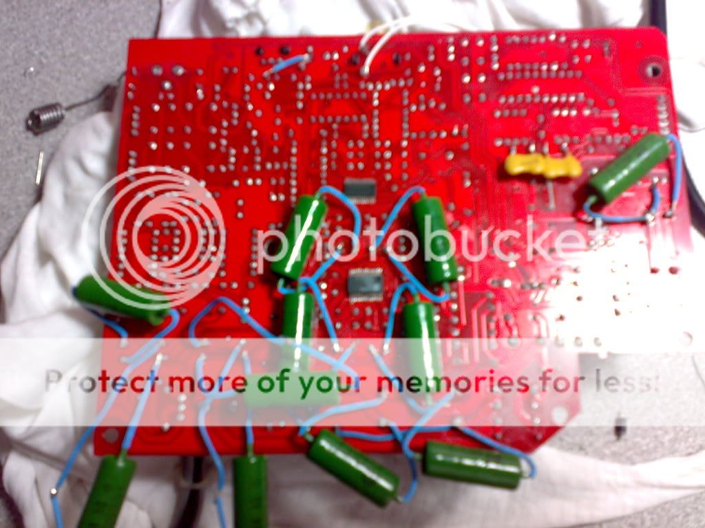
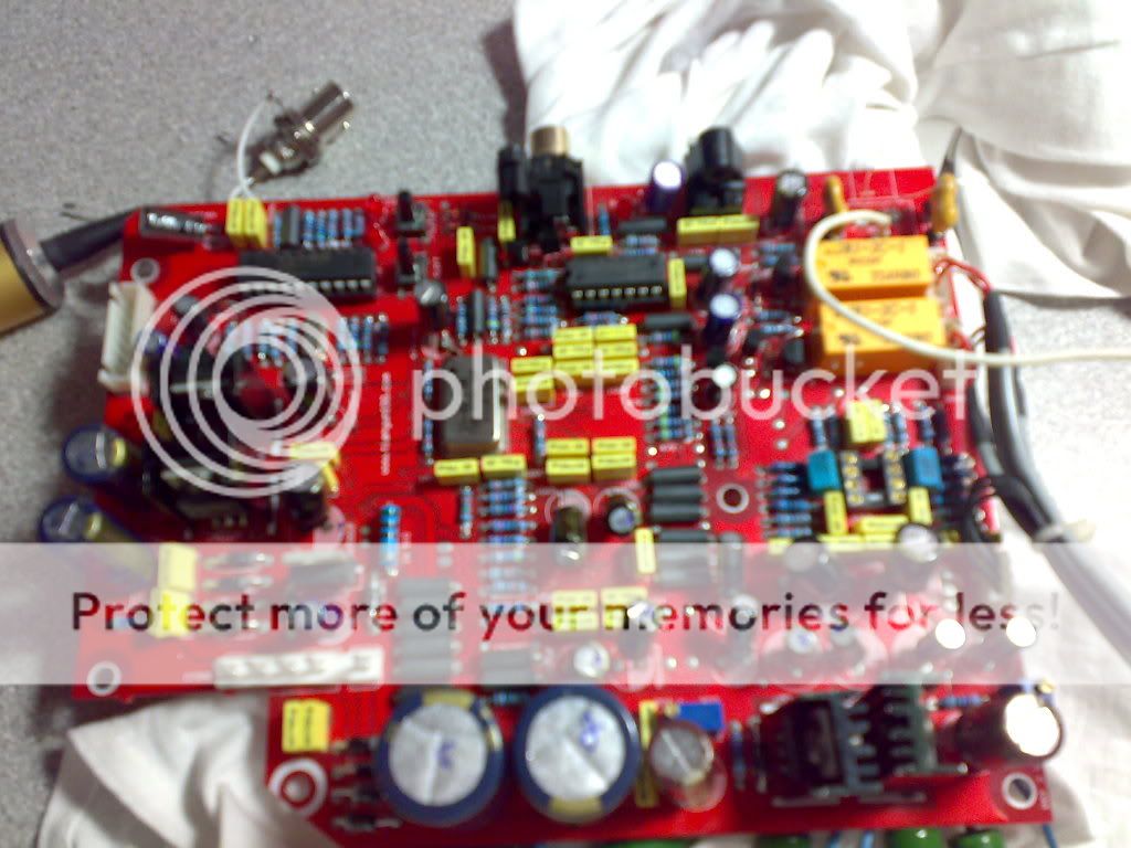
I have added a BNC plug in parallel to the Coaxial input, as I found the coaxial is way better than optical. I am using Canare 75 ohm cable with Canare 75 ohm plugs, both coaxial and BNC.

Here comes the photo. sorry for the camera photo such cant shoot clearly on short range.

22112008111.jpg


22112008113.jpg
 
Nov 24, 2008 at 12:02 AM Post #110 of 428
Hi CC,

You certainly have a unique parts selection happening on your Zero. I've done a pile of reading on BNC vs SPDIF jacks....it's not as easy as simply adding a BNC jack...have a look at DIY forum for exhaustive talks about pulse transformers, impedance mismatches etc etc.....after wading through pages of this stuff I decided BNC wasn't worth the effort for the tiny gain in SQ over a well made coax and a close to 75 ohm RCA jack.

That's my findings at least. I think with a hi quality well made glass TOSlink optical has the better SQ since impedance isn't a factor.

IMO at least. I do prefer COAX for the main rig...go figure.
smily_headphones1.gif


300 hours from now CC...that lack of sleep you are experiencing now only gets worse ...sorry buddy
biggrin.gif


Peete.
 
Nov 24, 2008 at 5:45 AM Post #111 of 428
Well those Zobel networks and the ripple wavefront are technical jargons that scare away alot of people. Some of the CD mod I saw remove those transmission networks. I kept it simple, in that the transport resistor matching is network with 91 ohm and 390 ohm.
 
Nov 24, 2008 at 4:22 PM Post #112 of 428
I hope someone can help me out here. What is the voltage u measure at the 4 nos of 100uF supplying the AD1852. Are they all 5 V ?

tks.
 
Nov 24, 2008 at 6:35 PM Post #113 of 428
Well I did the caps and diodes on the main board last night, and damn those traces are thin. I had a few of the solder pads lift up while desoldering but got them to lay down pretty well, except for one that got a bit mangled at one of the big 4700uf caps, I thought I had it bridged with some extra solder pretty well.

However when I fired it up to test it I was only getting a weak output from the rca, and the headamp section led was slow to come on and shut off a few times. I could wiggle the cap with the iffy solder joint a little and get it to come on. It was late last night so I left it that way so I could get after it today and start fresh.

I'm hoping to be able to either redo the joint and try to get better contact with the trace, or maybe use a jumper wire from the cap leg to a leg of the closest component on the same trace. Otherwise I guess its new DAC time, hehe, oh well always a risk.
 
Nov 24, 2008 at 11:10 PM Post #114 of 428
Just use a multimeter and check the continuity between the neighbouring joints.
 
Nov 25, 2008 at 1:23 AM Post #115 of 428
Quote:

Originally Posted by ccschua /img/forum/go_quote.gif
Just use a multimeter and check the continuity between the neighbouring joints.


I've mostly fixed the flickering power issue, it was a bad connection at one of the 4700uf caps. I'm still getting very weak and staticky output though. Lots of static when I turn the pot on the headamp, and the headamp shuts itself off near full volume. I guess I have to keep on checking continuity everywhere and hopefully I find it.
 
Nov 25, 2008 at 5:07 AM Post #117 of 428
Quote:

Originally Posted by ccschua /img/forum/go_quote.gif
I hope someone can help me out here. What is the voltage u measure at the 4 nos of 100uF supplying the AD1852. Are they all 5 V ?

tks.


Hi CC,

As far as I know those four caps are all 5V and under. If you look at the 2 voltage regulators nearby, the silk screening on the pcb is as follows +3.3V and +5 V. I have no idea what caps of those 4 are on the 3.3V circuit. I would need to pull the board and measure it to find out.

I think someone else made those measurements a couple of weeks ago but I can't recall who it was or what the results where.

Peete.
 
Nov 25, 2008 at 3:10 PM Post #118 of 428
Anyone know the value of those little yellow box caps by chance? I think I may have cooked one when the screw that holds the tip on my iron laid up against it.

edit- nvm, I was posting from work and couldn't look at the caps, I see they are all different values, but I don't think thats the problem, I think I might have gotten one of the 4700uf caps too hot when I was messing around with it, so I'm going to order some replacements and hope for the best. I had to replace the 47uf cap next to the big caps because the voltage regulator marked lm117t 5 got blazing hot really fast after I had tried to resolder the joints on the cap, and the leds on the DAC board didn't even come on. Replacing that cap returned the regulator to a normal temp and the leds came on again, so thats why my suspicion is at the large caps. Would a burnt cap cause weak volume and static? I'm hoping I found my flub.
 
Nov 26, 2008 at 9:32 PM Post #119 of 428
Hi,
Basically just getting into this hobby. I have a question about the bypass caps. If I had a 100 uF cap in place and bypassed it with a 100 uF cap, could I accomplish the same thing by pulling the original cap and replacing it with a 200 uF?

The 2 Caps are just soldered side by side on the same pads, correct? I'm trying to grasp what is going on here.
 
Nov 27, 2008 at 1:13 AM Post #120 of 428
Quote:

Originally Posted by les_garten /img/forum/go_quote.gif
Hi,
Basically just getting into this hobby. I have a question about the bypass caps. If I had a 100 uF cap in place and bypassed it with a 100 uF cap, could I accomplish the same thing by pulling the original cap and replacing it with a 200 uF?

The 2 Caps are just soldered side by side on the same pads, correct? I'm trying to grasp what is going on here.


Hi Les,

Well not exactly....what you are talking about is adding additional filtering capacity for that particular spot. The electrolytic (aluminum can radial type) cap is bypassed with a high quality PIO or film and foil, poly foil...Teflon and foil...that is anywhere from 10 to 100 times smaller in capacitance to the electrolytic cap you plan on bypassing.

The advantages with bypassing are multileveled, unrestricted high frequency handling (a known drawback of any electrolytic type) or passing, lowered ESR through parallel connection, and additional filtering of unwanted noise components in the signal or power supply lines. The film and foil cap can also voice that part of the circuit to a small degree. Some find this desirable while others do not. I prefer the caps behave as neutral as they can on the original signal, of course that's almost impossible but it can be aspired to.

You can tune your unit (
biggrin.gif
) with careful selection, sizing and placement of your electrolytic/film cap networks in virtually anything that makes music reproduction possible, DAC's, H/Amps, Preamps, Amps, IPOD (LOL), etc etc...the real trick is knowing what to use and where to use it.

All of this is IMO of course
smily_headphones1.gif


Peete.
 

Users who are viewing this thread

Back
Top