


pravous
100+ Head-Fier
With a growing tube collection I decided I needed a way to test and match vacuum tubes. While there are many options out there I decided to order and assemble an Etracer. If you are curious you can check out the website here: Etracer website. The Etracer is a vacuum tube tester that you hook up to a computer which allows you to test just about anything you want to know about a tube. The basic options are a quick scan (results compared to what expected new tube values would be), full scan (complete trace of curves along all voltages), and corner scan (edge case testing at maximum voltages). You have two options when buying an etracer, diy make it yourself from a kit, or have them assemble the kit for you. I chose to assemble the kit myself.
Here is what arrived on my doorstep this past Thursday.

Despite being opened by customs everything was in good order. The basic contents are a bag of hardware (connectors, pins, tube sockets, banana jacks, hookup wire)
a Meanwell power supply, complete chassis and the pcb with the heart of the Etracer (pcb comes already soldered and completed).

Not included with the kit are screws to attach the tube sockets, 5mmx20mm slow blow fuse, a usb A cable to connect the unit to the computer and an optional 80mm fan. I went ahead and ordered all of the above before the kit arrived. I had also read that the provided tube sockets are not the best so I went ahead and ordered some belton and amphenol 9 pin, 8 pin octal, 5 pin ux5 and a 4pin socket since these are the one I will be primarily testing. I also ordered some 4 inch Hammond handles which I saw in another build video.
First up was drilling some holes in the chassis side plates to accept the new handles.

Next up was wiring up the back plate from the IEC power socket over to the power supply.

A couple of notes here. The instructions for this step are quite basic. If you are not familiar with a combo iec inlet, fuse holder, switch assembly you will have to break out the multi meter and use the continuity tester to figure out how to connect the tabs. I opted to use spade connectors and colored solid core wire I had left over from my Bottlehead crack build. I covered the spades with heat shrink as well. The instructions vaguely mention that the USB connector may make a ground connection with the chassis but I opted to make a direct ground connection which you will see connected later. On top of the power inlet is a USB header which is provided with the kit. On the right is the 80mm fan, optional but I decided to go with a noctua. If you do decide to add a fan you will need a 3pin model, the etracer will not work with a 4 pin pwm fan. Once the back panel is all set you can go ahead and start putting the chassis together.
Here is the back view with the back, bottom and side panels all together.

Below is the view from the front showing the power inlet connected to the power supply mounted on the side panel to the right.

You can also see the ground connection (white wire with yellow heat shrink) connected to the motherboard stand off and thus the bottom chassis plate. The usb header connects to the back of the pcb to the right of the ground connection. Make sure to plug in the usb header before screwing in the back plate as the spacing is pretty tight. The red and black wires on the top right connect the iec inlet to the power supply with a molex connector. The connector and pins are provided with the kit. Making these molex connections were the biggest time sink for me. Doable but very time consuming. Last is the fan connection, the instructions let you know that the polarity of the pins on the pcb are reversed from a normal computer fan connection. The solution requires either breaking off the lock tab on the pcb or cutting the fan wires and resoldering. I opted to break off the lock tab and reverse the connector that way.
Now we have power to the power supply and need to get it to the etracer pcb.

Another molex harness is made and along the way you need to adjust a potentiometer on the power supply and dial it into 29V. Once the power supply is hooked up to the pcb the power section is done.
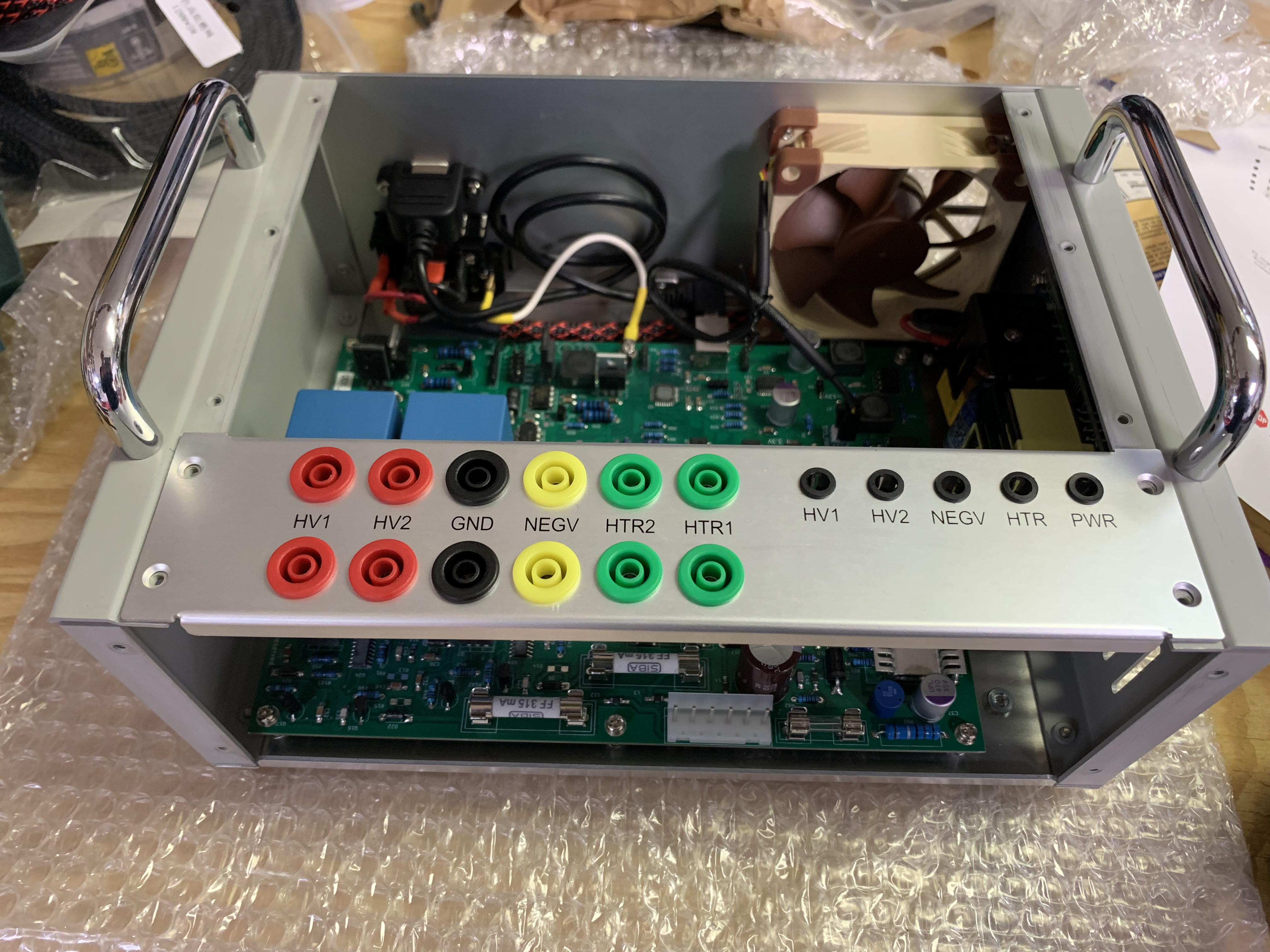
Next step in the front top plate which contains the indicator leds and the banana jacks that will connect to the tube sockets.

Two more molex bundles to make, one for the leds and one from the pcb to the banana jacks.


Test power up and power led and fan are working!

Last thing left is to make the top plate which consists of banana jacks and tube sockets. Very time consuming, I elected to just wire up the 4 tube sockets that I am looking to test.

The kit comes with stranded hook up wire which would not be my first choice. Can be a major pita in terms of fishing it through the tube socket pins. The black shrink tubing locks in the ferrite beads provided with the kit.
Final piece before mounting the top plate is a paper tray which goes below the top plate and catch any metal shaving that might be created by inserting and removing tubes from the sockets.

And after the better part of a day the Etracer is complete!
![IMG_2975[2070].jpg](https://cdn.head-fi.org/a/11718093.jpg "IMG_2975[2070].jpg")
Probably the most involved diy project I have made to date. In retrospect the $180 fee to have them build it for you seems like a pretty good deal. On the other hand having built it myself I was able to add some tweaks in the handles and better tube sockets. Pretty wiped after building and typing this all up so I will get into the software and actual tube testing tomorrow.
Here is what arrived on my doorstep this past Thursday.
Despite being opened by customs everything was in good order. The basic contents are a bag of hardware (connectors, pins, tube sockets, banana jacks, hookup wire)
a Meanwell power supply, complete chassis and the pcb with the heart of the Etracer (pcb comes already soldered and completed).
Not included with the kit are screws to attach the tube sockets, 5mmx20mm slow blow fuse, a usb A cable to connect the unit to the computer and an optional 80mm fan. I went ahead and ordered all of the above before the kit arrived. I had also read that the provided tube sockets are not the best so I went ahead and ordered some belton and amphenol 9 pin, 8 pin octal, 5 pin ux5 and a 4pin socket since these are the one I will be primarily testing. I also ordered some 4 inch Hammond handles which I saw in another build video.
First up was drilling some holes in the chassis side plates to accept the new handles.
Next up was wiring up the back plate from the IEC power socket over to the power supply.
A couple of notes here. The instructions for this step are quite basic. If you are not familiar with a combo iec inlet, fuse holder, switch assembly you will have to break out the multi meter and use the continuity tester to figure out how to connect the tabs. I opted to use spade connectors and colored solid core wire I had left over from my Bottlehead crack build. I covered the spades with heat shrink as well. The instructions vaguely mention that the USB connector may make a ground connection with the chassis but I opted to make a direct ground connection which you will see connected later. On top of the power inlet is a USB header which is provided with the kit. On the right is the 80mm fan, optional but I decided to go with a noctua. If you do decide to add a fan you will need a 3pin model, the etracer will not work with a 4 pin pwm fan. Once the back panel is all set you can go ahead and start putting the chassis together.
Here is the back view with the back, bottom and side panels all together.
Below is the view from the front showing the power inlet connected to the power supply mounted on the side panel to the right.
You can also see the ground connection (white wire with yellow heat shrink) connected to the motherboard stand off and thus the bottom chassis plate. The usb header connects to the back of the pcb to the right of the ground connection. Make sure to plug in the usb header before screwing in the back plate as the spacing is pretty tight. The red and black wires on the top right connect the iec inlet to the power supply with a molex connector. The connector and pins are provided with the kit. Making these molex connections were the biggest time sink for me. Doable but very time consuming. Last is the fan connection, the instructions let you know that the polarity of the pins on the pcb are reversed from a normal computer fan connection. The solution requires either breaking off the lock tab on the pcb or cutting the fan wires and resoldering. I opted to break off the lock tab and reverse the connector that way.
Now we have power to the power supply and need to get it to the etracer pcb.
Another molex harness is made and along the way you need to adjust a potentiometer on the power supply and dial it into 29V. Once the power supply is hooked up to the pcb the power section is done.
Next step in the front top plate which contains the indicator leds and the banana jacks that will connect to the tube sockets.
Two more molex bundles to make, one for the leds and one from the pcb to the banana jacks.
Test power up and power led and fan are working!
Last thing left is to make the top plate which consists of banana jacks and tube sockets. Very time consuming, I elected to just wire up the 4 tube sockets that I am looking to test.
The kit comes with stranded hook up wire which would not be my first choice. Can be a major pita in terms of fishing it through the tube socket pins. The black shrink tubing locks in the ferrite beads provided with the kit.
Final piece before mounting the top plate is a paper tray which goes below the top plate and catch any metal shaving that might be created by inserting and removing tubes from the sockets.
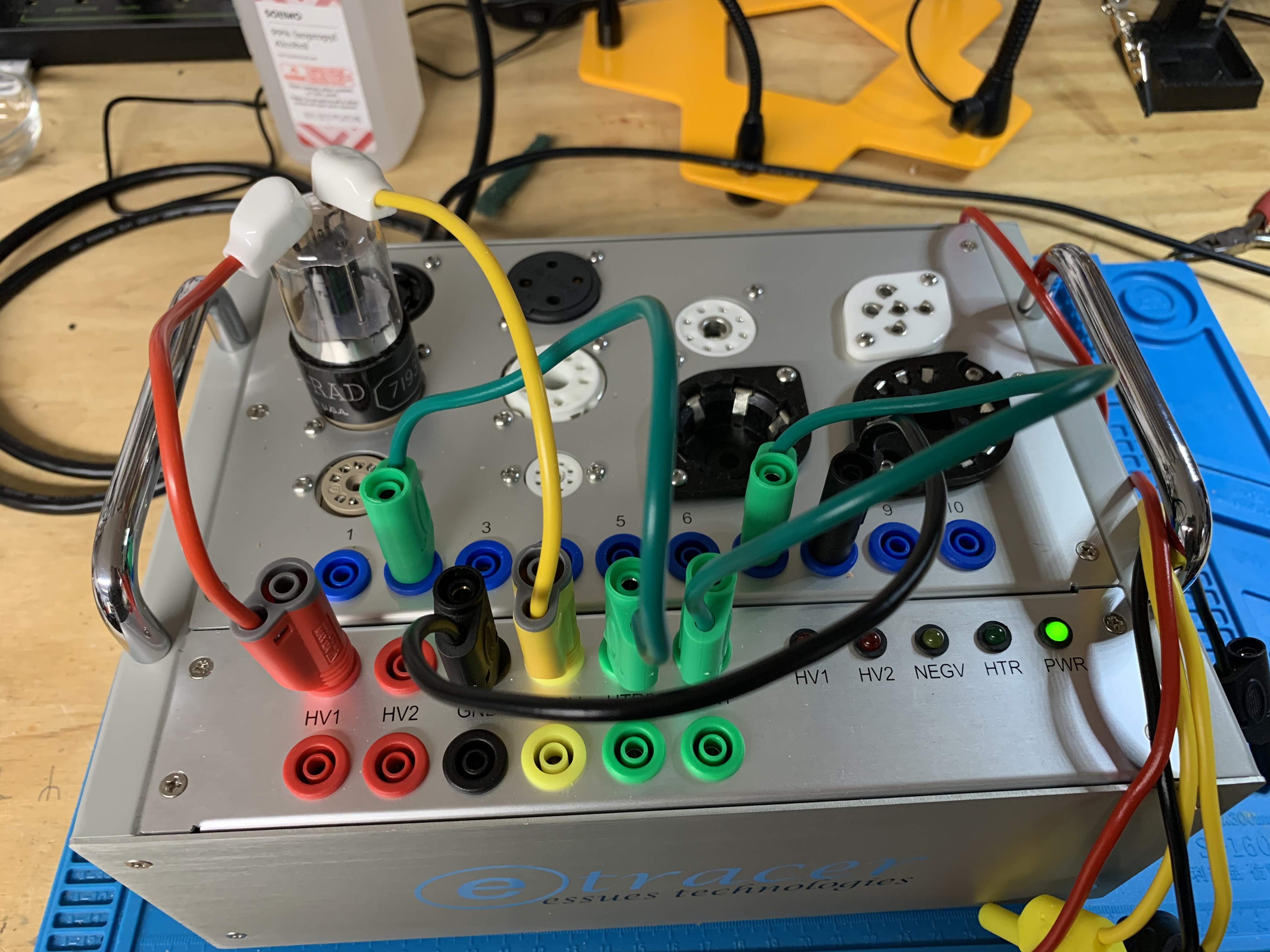
And after the better part of a day the Etracer is complete!
Probably the most involved diy project I have made to date. In retrospect the $180 fee to have them build it for you seems like a pretty good deal. On the other hand having built it myself I was able to add some tweaks in the handles and better tube sockets. Pretty wiped after building and typing this all up so I will get into the software and actual tube testing tomorrow.


")
