Hi guys,
I'll be doing the classic newbie thing and introduce myself with a silly question.
")
I just started getting together the parts necessary for the build and I messed up something in the communication
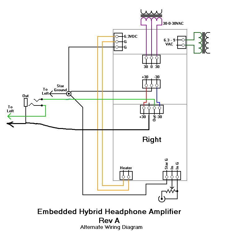
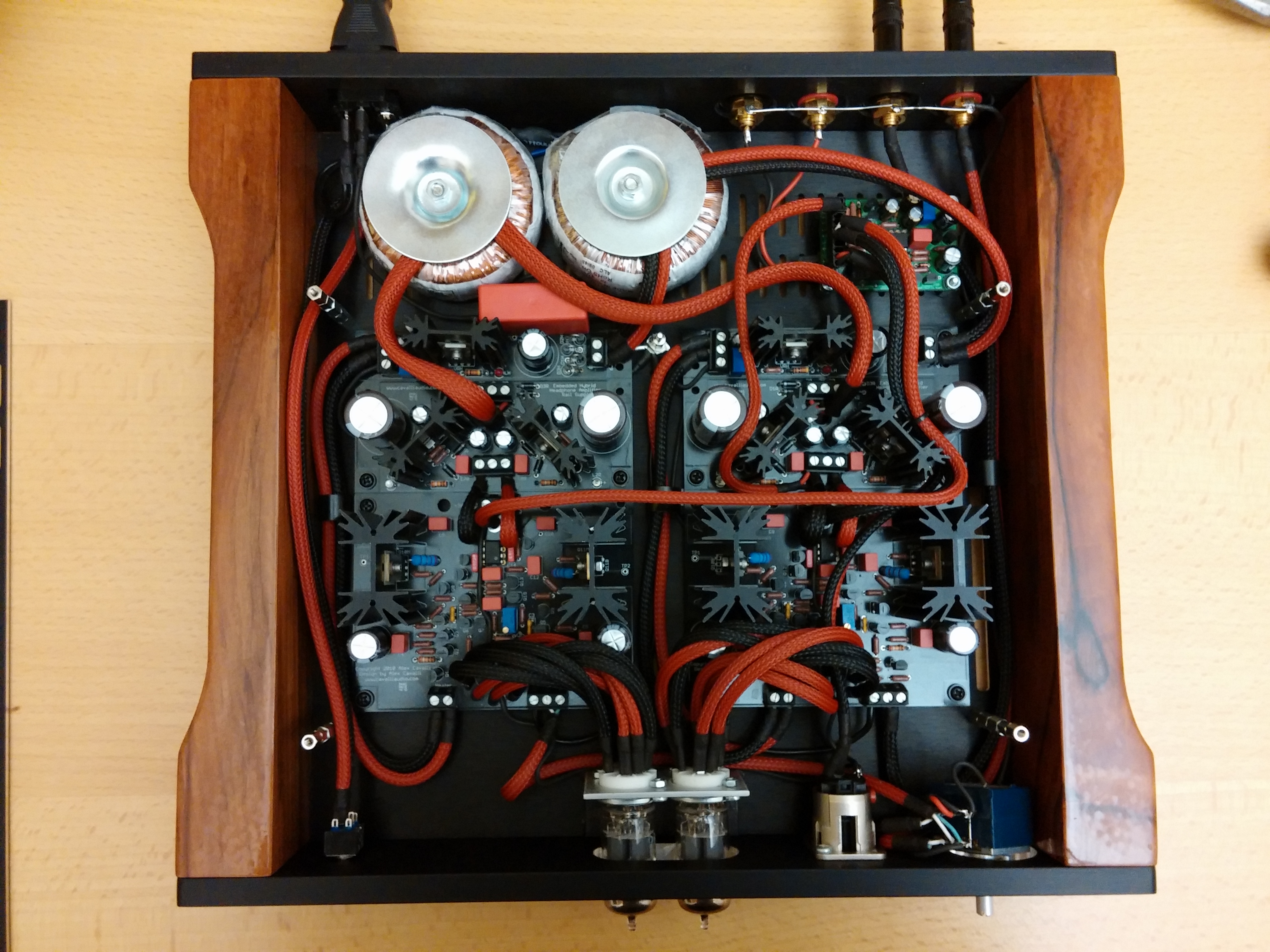
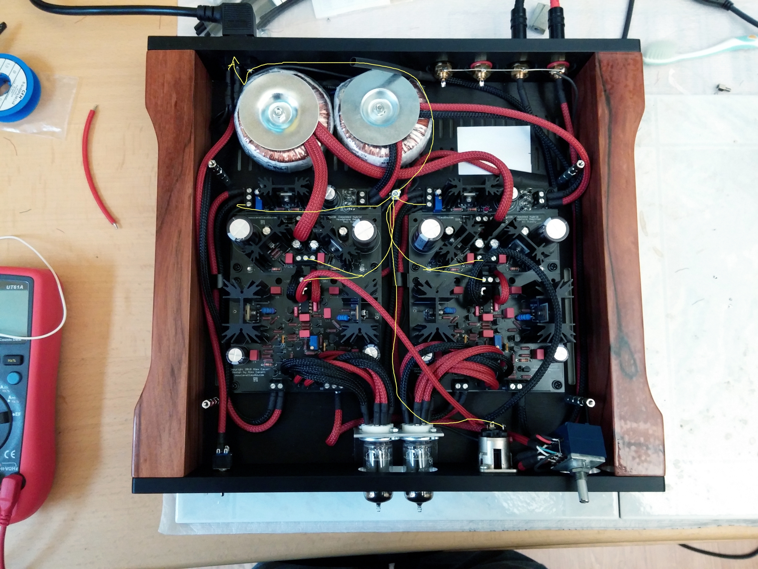
with my supplier about the transformers, so instead of getting a center tapped 30-0-30 toroid,
I got two regular 30V (10 VA). Can I make them work somehow as a + - supply or do I have to
order a new transformer? Unfortunately I made the mistake, so I can't claim a refund.
Any ideas?
One more thing the 1N5313 diode no longer seems available.
Can I replace it with 1N5314? They are quite close in specs.