stringgz301
100+ Head-Fier
- Joined
- Sep 11, 2009
- Posts
- 218
- Likes
- 22
I found that the Amperex a-frames biased significantly differently from all my other tubes. You may need to recheck it after installing the Tele's.
How do they sound compared to the - for example - telefunken 6GM8's?
OK. So solved one problem. Had the rails transformer improperly wired. Corrected this and started it up again. Heater and rails power supplies test good, with corrected DC output from heater PS and rails PS. DC offset 0. Tubes bias properly.
Have a different hum. Music plays ok, but when it stops have background hum. Independent of volume pot. Could this be the dreaded ground loop?
I've just started my setup, and am having a problem with the heater supply. I'm using the tranny from the Glassjar kit, an Avel Y236101, 9VAC/1.65A.
I've got it wired with the red/black wires to one board, and the yellow/orange wires to the other. Both boards are reading 13.65VDC at TP3, and the output
is at 12.65VDC. I cannot get the output to change at all. Do I have the tranny wired wrong? Should I pair black/orange and red/yellow? Have I blown the reg's?
I'm stumped.
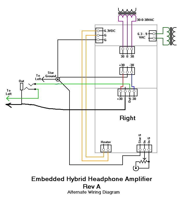
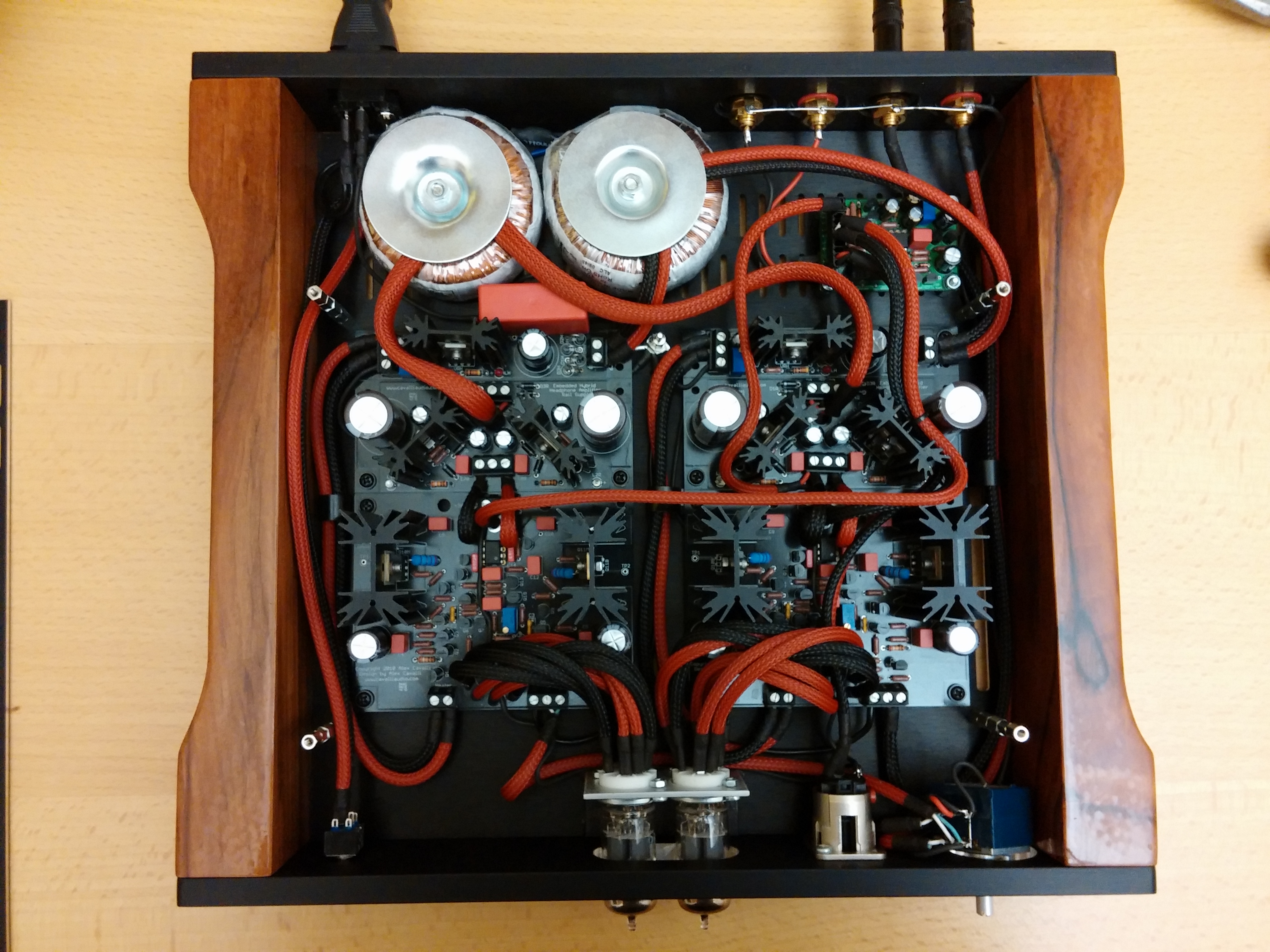
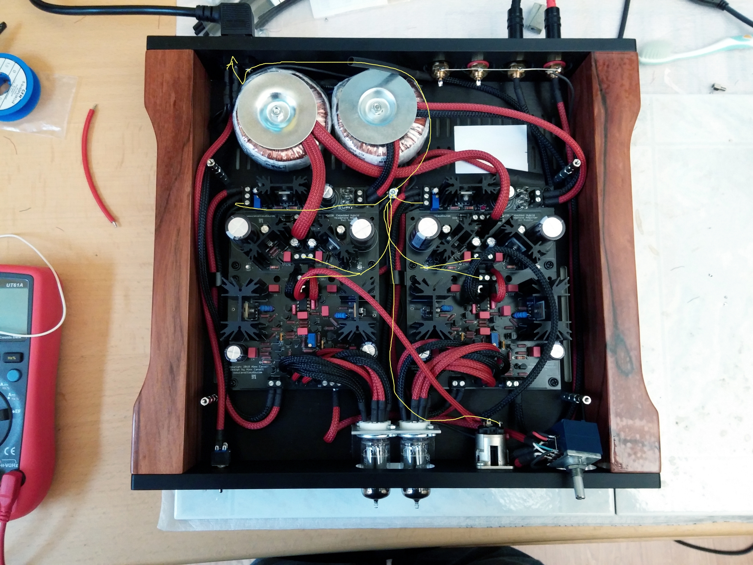
Grounding: right now, each board has 3 sg grounds (I'm using the alternate wiring scheme connection at the front of the board), that all connect to a central terminal. That ground is isolated from the case (should it be?). The IEC ground is connected to the case.
Yes. That central terminal needs to be connected through a ground loop breaker to the chassis. Use a 10 ohm/10Watt wirewound resistor with a Class X or Class Y 250VAC capacitor.
A bit of question mark for me is the Khozmo attenuator (4 channel). It has 4 inputs plus a ground connector, and 1 pair per channel of output and ground connections. I currently have it wired like the attached (Pic from john mcclean, my annotations, using wire leads instead of his diy bridge between ground connections). Not sure why he has 2 leads connected to each output ground connection. Also, not sure why the bridge is required given that on each board the IG connects through the ground plane to SG.
Any and all help is much appreciated.
No idea about the multiple leads on the ground pins.. leads to a switch or something else perhaps?