


Alcaudon
100+ Head-Fier
- Joined
- Nov 3, 2006
- Posts
- 204
- Likes
- 35
Quote:
Are you going to use MOSFETs or BJTs?Most of what I have read in various forums indicates "air wiring" MOSFETs is not necessarily a good idea. I am not sure about BJTs.
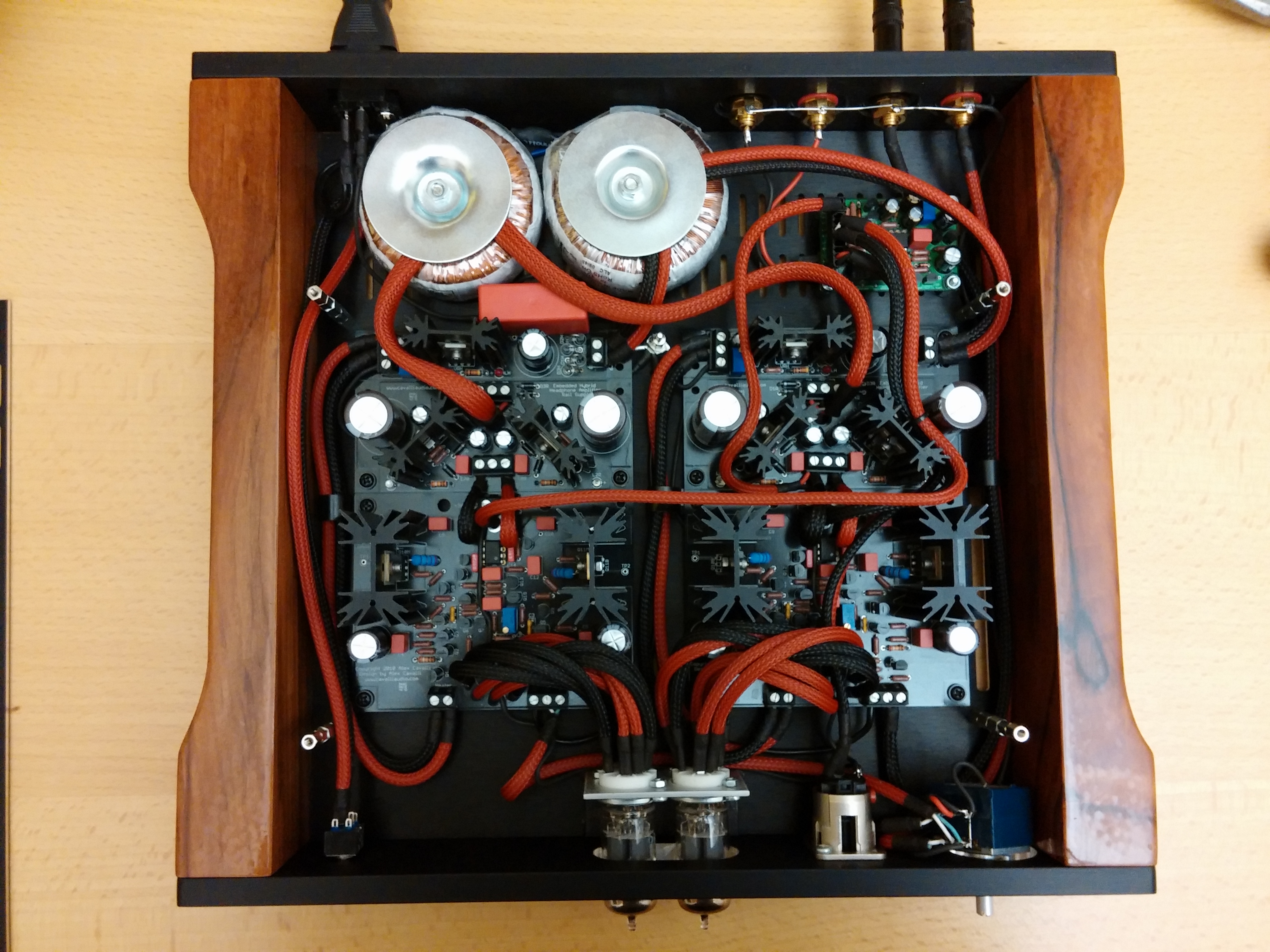
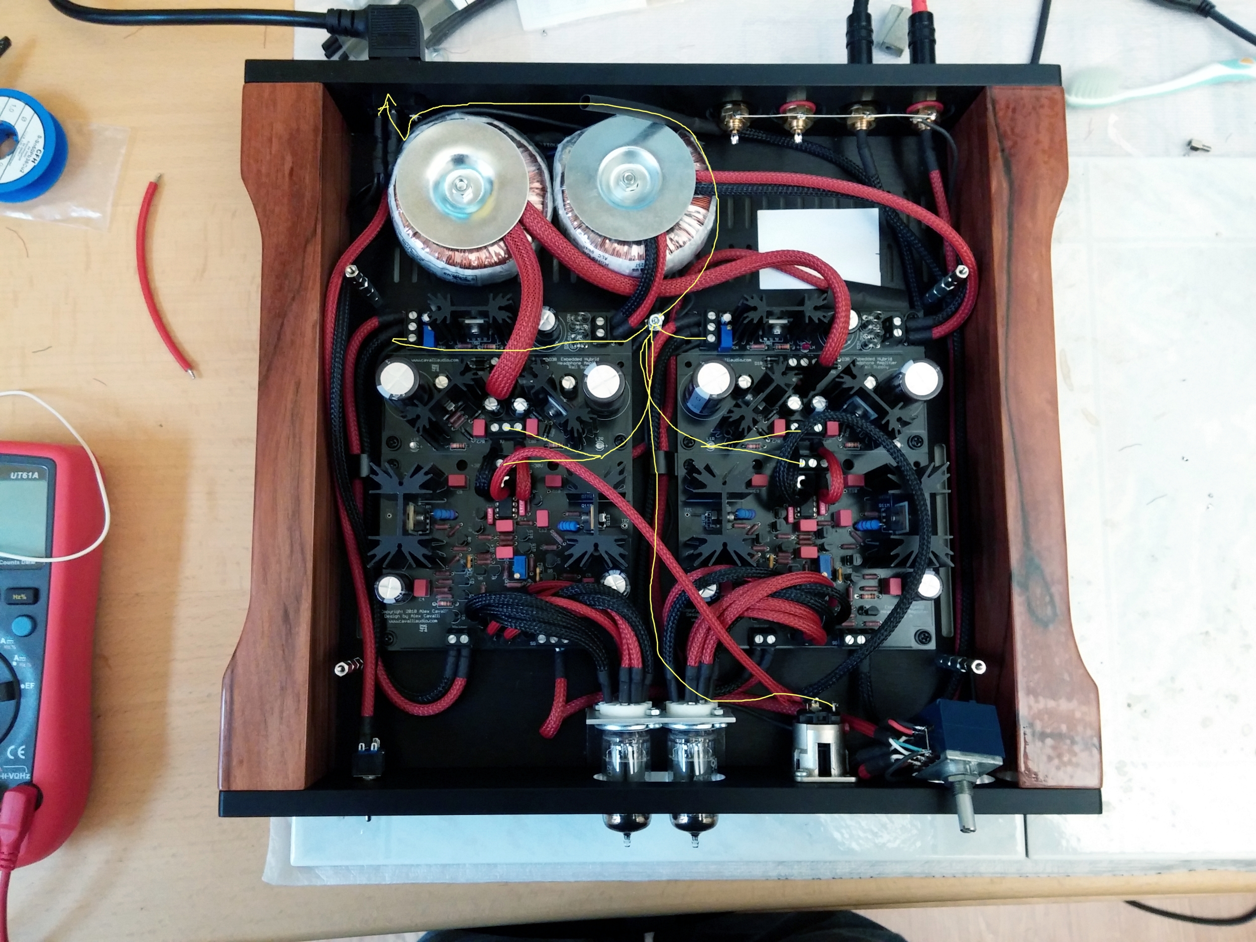
Mosfets. Yes, I've read the same, this is what holds me back. Guess that I'll have to stick to a "conventional" building and forget about low profile and tubes sticking out

") I hear no difference to my M³.
I hear no difference to my M³.
