EHHA Rev A - Interest Thread
Aug 20, 2011 at 3:59 PM Post #1,366 of 1,752


Quote:
What do you mean when you say group terminal?


You can measure DX offset across O2 and O3 of the terminal block where power enters the amp and output exits. What is the measurement at that point?


That's where I measured from. It was the voltages I said above, around 3.5ish.
 
 
Aug 20, 2011 at 9:25 PM Post #1,367 of 1,752
Do you have an auto ranging multimeter? If not, what range was it set at?

Just trying to establish a baseline and ask the obvious questions first.

Did you verify the correct orientation of the DC servo opamp?
 
Aug 23, 2011 at 5:04 PM Post #1,369 of 1,752
I'm off at college now...couldn't bring the amp along
triportsad.gif
. I will be back for labor day weekend, but I've had to put the project on hold until then. Thank you so much for your help so far, it means alot of have some sort of support line.


Sep 3, 2011 at 11:59 AM Post #1,371 of 1,752
I gotta find a multimeter since I conviently left mine back at school...but as for IC1, it is currently oriented(Tube is bottom center for reference), with the dot on the op amp in the lower right.  
 
Sep 3, 2011 at 12:11 PM Post #1,372 of 1,752


Quote:
I gotta find a multimeter since I conviently left mine back at school...but as for IC1, it is currently oriented(Tube is bottom center for reference), with the dot on the op amp in the lower right.  


Okay, that is the correct orientation.
 
Most importantly, how are you establishing ground in your test setup? How do you have the board wired up in your test setup? A pic or two would help as well.


Sep 3, 2011 at 12:18 PM Post #1,373 of 1,752
I just installed the 2 missing components on the second board, after I wire everything up completely I'll take a couple pictures.
 
Sep 3, 2011 at 1:38 PM Post #1,374 of 1,752
Well partway through the wiring I decided to fire it up for kick and giggles.
 
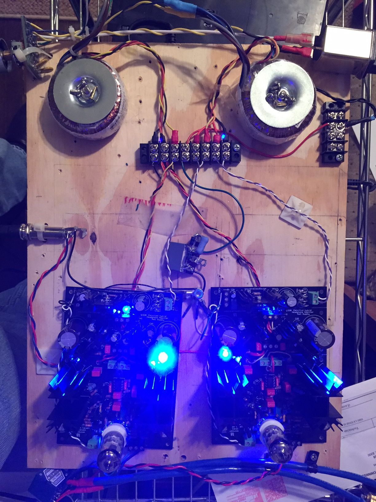
I have a 2 stage power switch installed, so I let the tubes heat for a minute or two before turning the amp on. When I turned the switch to both on, the board I just finished light up, at that point I remember I installed LEDs under the tubes.
 
So a new symptom to add to the list is LED under board not lighting for the problem board.
 
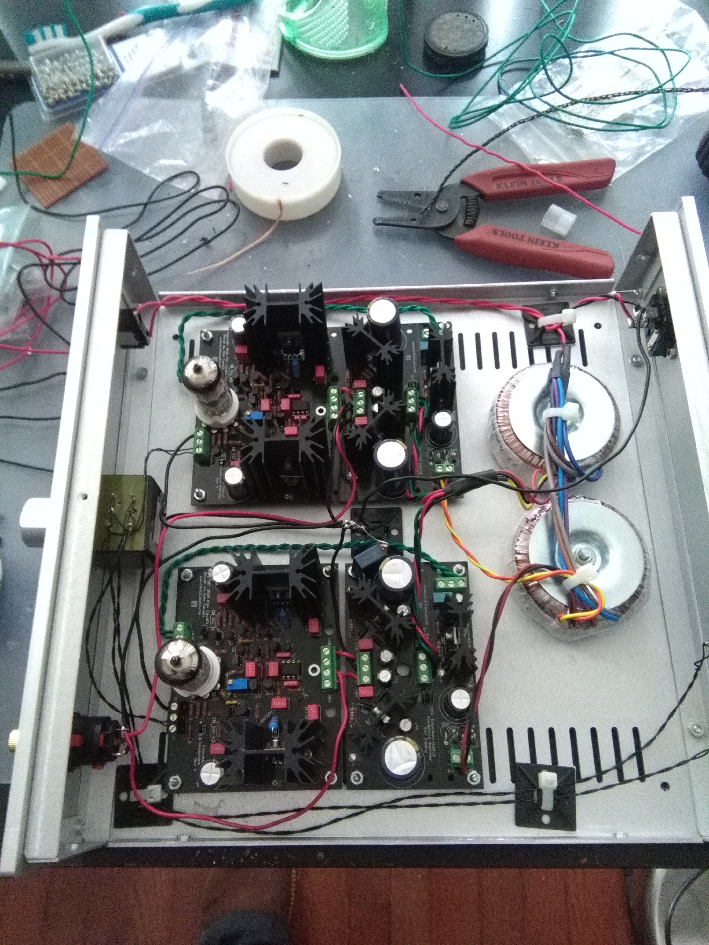
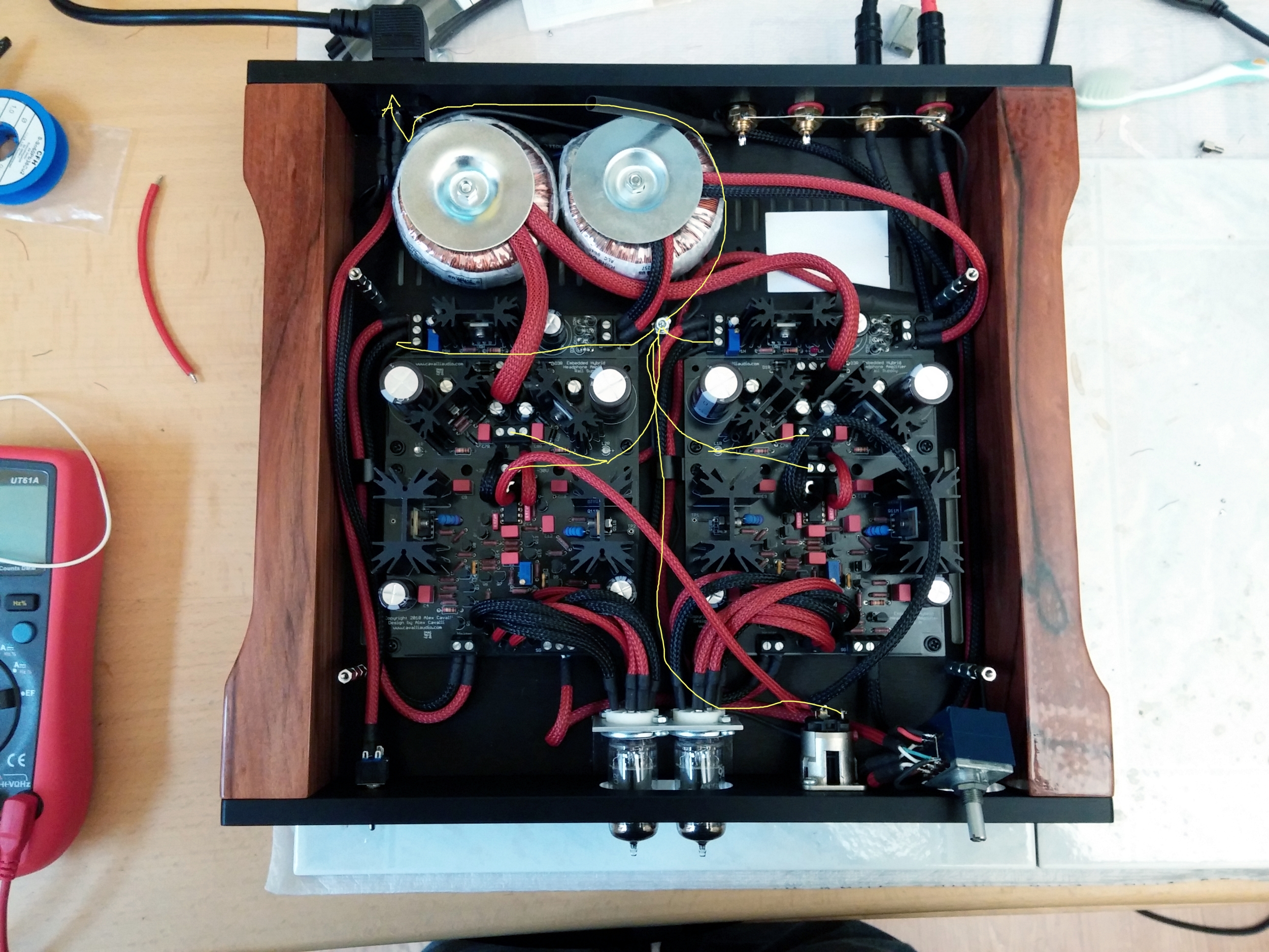
Then I broke out my dads DMM, and the VDC between out and ground on the second boards terminal block(the one with working led under the tube) was around 2 mV and still dropping.
So then I measure LED+ to LED- just for fun, on the working board it measures 2.8V, on the problem board it measure around 0.7V.
 
Pic to come, I promise. Just gotta find the cable to hookup the camera.
 
By the time I finished typing this, I checked dc offset again, and it had dropped to .5 mV.
 
Sep 3, 2011 at 5:20 PM Post #1,375 of 1,752
Sorry for the poor quality...phone camera.

 
Sep 3, 2011 at 11:00 PM Post #1,377 of 1,752
While you are measuring, also measure from +LED to ground and -LED to ground. The goal is to see which of the rails is being pulled down and then find out where (or which part or solder bridge) is doing the pulling.

No offense, but, that picture is worthless. I swear, a decent point and shoot should be standard issue for these projects. Sometimes they are as equally valuable as a decent iron. :D
 
Sep 5, 2011 at 10:33 AM Post #1,378 of 1,752
Alright, found a better camera.

 
Voltage on the problem board for the LED, from LED- to G measures about -200 mV, and LED+ to ground measures about 250 mV.
 
Voltage coming off PSU is +27 and -27
 
Sep 5, 2011 at 11:28 AM Post #1,379 of 1,752
Okay, that is much better. How about a couple of close-ups of the problem board? Which is it BTW (in the picture shown)?
 
Also, verify the orientation and correctness of V- and V+ (79L15 and 78L15). Make sure they are not accidentally swapped.


Sep 5, 2011 at 11:42 AM Post #1,380 of 1,752
BTW, you should tie your AC ground directly to the chassis first prior to attempting to use the ground loop breaker.
 
Scrap off a bit of the anodizing and attach using lock washers to ensure you get good contact with the bare metal. Once you have established a good connection between AC ground and the chassis, you can then use the ground loop breaker (if required) between signal ground and chassis ground. I generally make the AC ground connection a short segment of solid, lower gauge wire as close to the AC inlet as workable.


This will make the build safer.
 

Users who are viewing this thread

Back
Top