EHHA Rev A - Interest Thread
Jun 22, 2014 at 2:34 PM Post #1,651 of 1,752
Sathimas,
 
your description does confuse me...
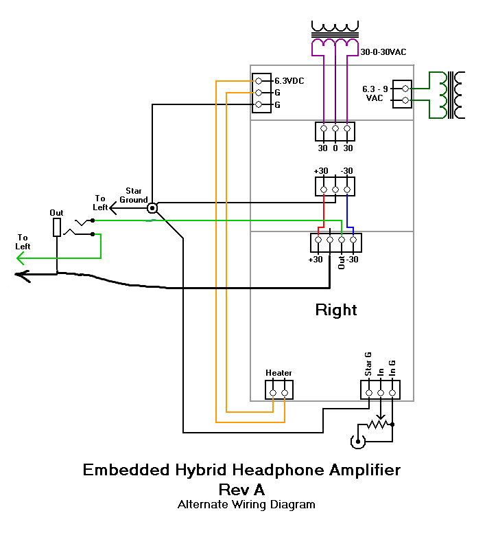
Is it 9V for the heater supplies or 12V? 12 V would be way too high for 6.3V heaters... I am using a 7V winding btw.
A regular 12V winding is 12-0, so you just hook it up to the heater supplies...
blink.gif

Or am I missing something?
 
Jun 23, 2014 at 11:34 AM Post #1,652 of 1,752
Forget what I wrote - it was just nonsense.
I have a 9-0V winding and two 30-0V windings.
 
I got the instructions from Rondo Mueller how to connect everything.
 
Still will need some more time before I can work on...
 
 
To cheer up my mind I did something quicker and more easy:

 
Aug 21, 2014 at 2:37 PM Post #1,655 of 1,752
I'm about to start doing preliminary case design. I know the dimensions of the complete boards are 150mm L x110mm W. What are the hole dimensions? My guess is 2.5mm in from the edges?
 
Aug 22, 2014 at 2:52 AM Post #1,656 of 1,752
Mullet,
 
the board size is correct, but 2.5mm from the edges wouldn't leave much for the hole itself.
I measured on the print from the Cavalli website, and according to this the CENTER of the
holes is 5mm from the edges with the hole being a bit over 3mm for an M3 bolt.
 
Hope this helps!
 
Aug 22, 2014 at 11:59 PM Post #1,657 of 1,752
Cool that's good to know. 5mm from the edges will help with my layout in Visio.
 
Oct 13, 2014 at 4:02 PM Post #1,658 of 1,752
Question for the guys who added in the E12 protection circuits...
 
Looking at the directions on the E12 website, it looks like the EHHA would fit in the 2 channel passive ground camp, but with the special situation of having a split power supply requiring 2 E12s. Am I correct in this assumption? The only hang up I have is that I'm not 100% sure about the EHHA having active or passive ground. So if it's passive then I'd only wire up L+ on one and R+ on the other, right? ...and If it's an active then L+ L- and R+ R-. Would I just tap from the star ground for L- and R-? Hopefully, its clear what I'm asking.
 
Also, my bias seems to move around rather than stay static. Once warmed up and set I seem to get about ±5mV fluctuations. Is this normal?
 
Oct 15, 2014 at 9:57 PM Post #1,659 of 1,752
Hey!
 
Just a heads up. I don't want to make this a pity party. I recently killed a pair of DT880s while using this amp. I did all the checks - no dc offset, biased both boards, and temp wired everything up. I used KSC75s to test with. Since, I had lovely music (with a tad of really low level buzz in the left channel) I decided to try out my DT880s. I figured I could fix it with a ground loop breaker and/or better tighter wiring. The DT880s had the buzz, but way way less. Anyways, after a long listening session, I had turned off the amp with the pot all the way down. Then I fired it up the next day with phones plugged in and volume turned down. Once I raised the volume I could hear the right driver had way less audio than the left. I tested the phones with different amps, same result. I know another builder had similar issues and killed a few earbuds. He mentioned that he even had the volume down and could measure voltage spikes on power up and power down. I'm glad I'm going to be implementing E12s in this build to protect my other phones. I do realize that others haven't used E12s so it must be something else that caused it -- I'm using a crappy 1/8 jack for my signal output.  D'oh!
 
Nov 5, 2014 at 5:26 PM Post #1,661 of 1,752
That is super cool. So I suspect this is based off the Rev A with BJT instead of mosfets. I suppose you only need one ±30v supply. Looks like you'll be able to minimize wires, etc. for star ground.
 
Nov 5, 2014 at 5:28 PM Post #1,662 of 1,752
If I'm able to get my chassis in order by the 10th, I'll be able to have things cased up by the NYC area meet on the 15th. I've never seen an EHHA at a NYC area meet, so I'm sure a lot of people will be interested in hearing it.
 
Nov 6, 2014 at 12:46 AM Post #1,663 of 1,752
  That is super cool. So I suspect this is based off the Rev A with BJT instead of mosfets. I suppose you only need one ±30v supply. Looks like you'll be able to minimize wires, etc. for star ground.

Hi,
 
this revision is totally based on the REv A , mosfet version ( that not appear in the pcb ) . The supply needed are the same than original 30v , plus the 12v for the lamps.I made a big work to minimize the pcb , it is now 170mm length. i will put some pictures when i'll finish it.
Thanks for the interest.
 
Nov 12, 2014 at 8:10 PM Post #1,664 of 1,752
I'm pretty much at the finish line with my EHHA Rev A. and as usual I've hit another snag. I've had some crappy luck with DIY lately. Keeps life interesting and I'm not giving up.
 
So here's the issue...
 
I didn’t have time to take pics, but I’ll try and explain… When each board is separate (not connected together via SG) and powered up... on the “bad” board I get around up to 30mV offset. It jumps around and almost zeroes out. The “good” board zeroes itself out. When I connect everything via a terminal strip using ethernet type copper wire I get about 1.3VDC offset. Not good. The “good” board still zeroes itself out. I’m pretty sure I have to look at the servo to see what is going on. What should I be looking out for? Do I need to think about re-wiring my SG?
 
I'm not sure if this is related to my earlier issue of killing headphones. I'm pretty sure I measured offset before plugging anything in. This was before I started casing things up. However, it's possible that it was related. At least at this point I have working E12s. I'm pretty bummed because I was hoping to have this ready for this weekend's NYC area meet and time is running out.
 
Nov 12, 2014 at 8:37 PM Post #1,665 of 1,752
I had a similar problem on one board of a semi-finished amp that I picked up on the FS forums. It turned out to be a cold solder joint on a resistor (R12 IIRC).  The original
joint looked fine, but when I put pressure on the resistor from the top, the solder completely pushed away from the board. Sneaky little %*#@.
 

Users who are viewing this thread

Back
Top