


Possede
500+ Head-Fier
- Joined
- May 3, 2005
- Posts
- 592
- Likes
- 10
Hello all, been a while since I've last posted. I am currently in the process of building a variable power supply that is capable of supplying a positive and negative DC voltage (to be used as part of my University project class). However, I have always wanted to build one anyway, as it can be used for a variety of low current situations, e.g. powering opamps, tinkering with arduino projects, etc.
I have already built a prototype circuit (on a stripboard) based on this bipolar design:

I used a toroidal transformer (dual secondary), with the following specifications:
Secondary Voltages: 2 x 25Vrms
Secondary Current Nom: 1A
Power Rating: 50VA
What I have done is attached both the secondary 0V outputs to ground, and the 25Vrms outputs to each side of the diode bridge. After the diode bridge and smoothing capacitors the DC voltage level was around +/- 40V [i.e. 29Vrms (unloaded voltage from secondary output) * 1.414 = 41.0Vpeak), then minus the voltage drop across the diode bridge, gives around 40Vdc]. This allowed the LM317 and LM337 to give their full range of rectified output voltage, +/- 1.2V to +/- 37V.
This design worked as expected, but now I am in the process of either buying a PCB, or designing and getting one made through my University. I recently came across the PCB's made by Twisted Pear Audio, i.e. the LCBPS and the LCDPS. I understand that the LCBPS is practically the same as the design I have used above,but uses two diode bridges to achieve the same result, and the LCDPS utilises two LM317s to create a separate dual positive rail power supply (is that the correct terminology?).
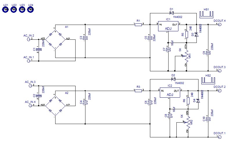
My question is regarding the design of the LCDPS, shown below.

As I already have a dual secondary toroidal transformer, what design would be best to use? Is it possible to achieve a positive and negative output from the LCDPS, by attaching the two middle connections to ground? i.e. the top connection is at a positive potential (wrt ground), and the bottom connection is at a negative potential (wrt to ground)? What are the advantages of disadvantages of one design over the other?
I appreciate any feedback that is given, and hope that this made sense. Let me know if anything doesn't!
I have already built a prototype circuit (on a stripboard) based on this bipolar design:
I used a toroidal transformer (dual secondary), with the following specifications:
Secondary Voltages: 2 x 25Vrms
Secondary Current Nom: 1A
Power Rating: 50VA
What I have done is attached both the secondary 0V outputs to ground, and the 25Vrms outputs to each side of the diode bridge. After the diode bridge and smoothing capacitors the DC voltage level was around +/- 40V [i.e. 29Vrms (unloaded voltage from secondary output) * 1.414 = 41.0Vpeak), then minus the voltage drop across the diode bridge, gives around 40Vdc]. This allowed the LM317 and LM337 to give their full range of rectified output voltage, +/- 1.2V to +/- 37V.
This design worked as expected, but now I am in the process of either buying a PCB, or designing and getting one made through my University. I recently came across the PCB's made by Twisted Pear Audio, i.e. the LCBPS and the LCDPS. I understand that the LCBPS is practically the same as the design I have used above,but uses two diode bridges to achieve the same result, and the LCDPS utilises two LM317s to create a separate dual positive rail power supply (is that the correct terminology?).
My question is regarding the design of the LCDPS, shown below.
As I already have a dual secondary toroidal transformer, what design would be best to use? Is it possible to achieve a positive and negative output from the LCDPS, by attaching the two middle connections to ground? i.e. the top connection is at a positive potential (wrt ground), and the bottom connection is at a negative potential (wrt to ground)? What are the advantages of disadvantages of one design over the other?
I appreciate any feedback that is given, and hope that this made sense. Let me know if anything doesn't!
