Dirt Cheap Stax Amp DIY - new schematic updated!
Mar 30, 2013 at 5:35 PM Post #61 of 104
Test done under 260V power supply. 

basically the 100K load resistor has about 1.3ma idle current in it. 
the lower transistor is taking about 4-5ma current( didnt bother to measure it, but its biased with one LED and 240 Re, so about 4-5ma).

Then I adjust the variable resistor of the upper transistor to make the output at 1/2 of Vcc. so the upper transistor is seeing about 2.7ma of current and yet it is a combination of CCS and emitter follower. 

I did some tests, absolutely flat FR from 20 - 20K with or without load

loaded with ECR500 ( with is about 100-120pf and i measured my pair of ECR500 is at 50Kohm at 18-20Khz), and with this circuit, the output is clean and did not roll off at 20k! Yet it's done without global feedback.

Now I have a circuit that is dirt cheap, simple to build, gloabl-feedback free and yet a very good performance. I will soon put all the stuff together in a box. 
 
Mar 30, 2013 at 5:46 PM Post #62 of 104
test: 
triangle wave, 1khz, +-100V output:


6KHZ square wave, because i only have fiio e10 as the source and the wav is 44.1Khz, so only 7 points per cycle, very poor resolution there, and this output is actually very close to the input:


saw wave at 1Khz, +-100V output:


1khz square wave, exactly the same as the input:

 
These are loaded output wave forms, so I feel very happy about the result I have so far, this little circuit is really something!
 
Mar 30, 2013 at 9:44 PM Post #63 of 104
I did a quick draw out of the circuit I have, if any of you feel this can be a interesting project, you can do a quick PCB prototyping. I don't mind if any of you want to produce it or not, I already post the schematic so I am sharing it and giving it away for free. But if anyone designed a PCB, please send me a few pieces, thanks!
 
Q1 Q2 Q3 Q4 I used TIP50, which is about $0.25 per piece.. so cheap
and Q5 can be any small bjt, as long as it can work around 20V. 
 
R3 R4 and R7 shall be trimpots, 500ohm
 
R3 and R4 sets the output voltage, R7 sets the idle current.
 
Output is taken from the upper side of R3 and R4


Mar 30, 2013 at 10:40 PM Post #64 of 104
Hi tyre
 
Had to change it a bit to get it to work...


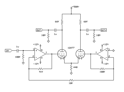
...doesn't look too bad in simulation...
 
This is 580V supply, 250V at the anode.
 
Input is 1V pk-pk, thru a 5k-5k divider into 100k. Loaded with 1M || 120pF. Opamps are NE5532
 

I'll have a look at the transistor one in a minute.

 
w
 
Mar 31, 2013 at 2:56 AM Post #65 of 104
Thanks for looking it over. Most of the part values were chosen somewhat arbitrarily. Any improvements that you think are worthwhile, feel free to add.
 
On a side note, this schematic of the SRM-001 by kevin gilmore might be of interest.
 
http://gilmore.chem.northwestern.edu/stxp.gif
 
Mar 31, 2013 at 1:54 PM Post #66 of 104
12at7 cannot handle 600 volts. In fact it can handle less voltage
than 6cg7. The only small tube that works is a 6s4.
 
Mar 31, 2013 at 3:10 PM Post #67 of 104
Thanks for looking it over. Most of the part values were chosen somewhat arbitrarily. Any improvements that you think are worthwhile, feel free to add.

On a side note, this schematic of the SRM-001 by kevin gilmore might be of interest.

http://gilmore.chem.northwestern.edu/stxp.gif


I am looking at the circuit as well, it's a great little circuit but it has op amps in it. My experience with op amps is that it requires another supply(12v) and also introduce high freq noises. I used to own sr001 and I really enjoyed its smooth sound, I guess the 130k resistor really helped to roll off the high end a little bit so I can't hear any harshness and its quite forging towards sources
 
Mar 31, 2013 at 6:11 PM Post #68 of 104
Quote:
12at7 cannot handle 600 volts. In fact it can handle less voltage
than 6cg7. The only small tube that works is a 6s4.

 
This is obviously a consideration and one which had not escaped me, but the quiescent plate voltage is 250V, the swing is 150V, and a 6SN7, which is what is shown in the tubecad circuit, is good for 450V. and is shown run at a B+ of 700V with its plate at 300V. Who am I to argue with Broskie, although it could be a typo.
 
Anyway I didn't seek to optimize the circuit, only show that it had some potential, and shouldn't be dismissed out of hand as lacking in HF response.
 
@wdiabc
 
Can you please check your schematic, I don't see how it is going to work as drawn.
 
w
 
Mar 31, 2013 at 8:42 PM Post #69 of 104
A 12AT7 has a rating of a maximum of 300 volts on the plate. Try it and you will see.
A 6SN7 has a rating of a maximum of 450 volts on the plate, with peak excursions exceeding 1000v.
 
6CA7 and 6SN7 are the best cheap tubes for this job.
 
Mar 31, 2013 at 11:10 PM Post #71 of 104
This is obviously a consideration and one which had not escaped me, but the quiescent plate voltage is 250V, the swing is 150V, and a 6SN7, which is what is shown in the tubecad circuit, is good for 450V. and is shown run at a B+ of 700V with its plate at 300V. Who am I to argue with Broskie, although it could be a typo.

Anyway I didn't seek to optimize the circuit, only show that it had some potential, and shouldn't be dismissed out of hand as lacking in HF response.

@wdiabc

Can you please check your schematic, I don't see how it is going to work as drawn.

w


Sorry the bias is not right. The capacitor connects to the upper side of 20k resisitor and provide bias via two 20k resistors to q3 and q4
 
Apr 1, 2013 at 6:22 AM Post #72 of 104
Quote:
 
Why would that be necessary? As I pointed out, not a consideration which had escaped me. Please read the posts before presuming to condescend.
 
w

 
not condescending.  But you should look at the real waveforms generated when you push
tubes like that past their limit.  Same thing with 6cg7. Top of the waveform gets very nasty
when you push the tube more than 300vpp. In addition to the high voltages, the Rp of the
tube very much effects the top part of the waveform. Serious compression occurs.
This is why current sources are better than the resistors.
 
Apr 1, 2013 at 9:51 AM Post #73 of 104
That is indeed why the Stax amps perform better with other tubes.  It's also not the 6SN7 that can do 450V, just the 6SN7GTA/B's.  The normal ones are identical to the 6CG7's in this regard. 
 
My super symmetry amp runs GTB's at +600V and they are fine but it was mostly chosen because of the transformer I used.   
 
Apr 1, 2013 at 5:46 PM Post #75 of 104
OK, point taken.

I can't get the Broskie circuit to work, the opamps are stuck on the rails.

wdiabc, I still can't get your circuit to work in the simulator.


I don't know why but simulators never likes my design. Haha. But I tested the circuit as shown and it works perfectly fine. R7 R3 and R4 are not accurate and needs to be trimpots. otherwise the bias won't be 1/2 of the power supply.
 

Users who are viewing this thread

Back
Top