bmwpowere36m3
100+ Head-Fier
- Joined
- Aug 17, 2008
- Posts
- 274
- Likes
- 3
Hey guys, I'm still new to the whole understanding electronic circuits but I'm making headway... I'm particularly interested in output coupling caps and their role in DAC's. I've recently iModed my iPod Mini so I can take advantage of the Wolfson WM8711 DAC for the time being.
First question, when typically used coupling caps block DC offset from entering the next circuit (that part I understand)... however are they always implemented like this:
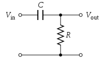
A capacitor in series with the "line" and a resister? In essence the implementation of a coupling capacitors is a high-pass filter, correct? Thus using f = 1 / 2*PI*C*R you can get the -3dB point (Hz). So my next question is how are these values (C & R) determined, are they arbitrary (as long as you get a f3 thats low enough) or is there more?
My understanding is choosing a f3 point that ~10X less than the lowest frequency of interest will reduce phase distortion, i.e. for audio circuit a f3 of ~2 would keep distortions out of the 20+Hz range.

I was reading Walt Jung's, "Picking Capacitors" and in it states that not only keeping a low f3 is important, but also minimizing impedance (ideally 10K or less)... opinions? This impedance I think he's referring to is the paralleled resistance of the input (pot in an amp, RL) to the "pull-down" resistor in coupling cap circuit (Rb).
So for my CMoY (10K pot) I'd need a ~any size Rb, but for a typical amp (50K pot) you'd need ~12K or less. So how would a 47uF & 10K(total R) for a f3 of .34Hz output coupling circuit sound/work? As I'm typically seeing Rb values ~47K and some DIY DAC's as high as 330K.
Now this info applied to my DAC, Wolfson WM8711 which states this as a recommend setup:

I understand C1 and R1, but R2 series resistor... it's only needed for a ham-fisted user you might ground the "line" when in use, correct? Preventing frying the unit. This covers HP filters, do DAC's typically also have LP filters to prevent high frequency oscillations due to over-sampling? Any recommendations?
I'm almost done, honestly, my last question deals with bypassing caps. I'm strictly interested in the ratio, if there is any, used between say two caps. I've read somewhere that the smaller (typically film) cap should be 1/10th or 1/100th the size of the larger cap (typically electrolytic).
That's it, thanks for any help

*edit* I actually did have one more question, where do you guys source Vitamin Q caps, I can only seem to find them on eBay for a "reasonable", i.e. cheaper than some guitar sites which are charging ~10-20 per cap. And what are reasonable prices, I'm looking for some (I think) 0.047uF.
First question, when typically used coupling caps block DC offset from entering the next circuit (that part I understand)... however are they always implemented like this:
A capacitor in series with the "line" and a resister? In essence the implementation of a coupling capacitors is a high-pass filter, correct? Thus using f = 1 / 2*PI*C*R you can get the -3dB point (Hz). So my next question is how are these values (C & R) determined, are they arbitrary (as long as you get a f3 thats low enough) or is there more?
My understanding is choosing a f3 point that ~10X less than the lowest frequency of interest will reduce phase distortion, i.e. for audio circuit a f3 of ~2 would keep distortions out of the 20+Hz range.
I was reading Walt Jung's, "Picking Capacitors" and in it states that not only keeping a low f3 is important, but also minimizing impedance (ideally 10K or less)... opinions? This impedance I think he's referring to is the paralleled resistance of the input (pot in an amp, RL) to the "pull-down" resistor in coupling cap circuit (Rb).
So for my CMoY (10K pot) I'd need a ~any size Rb, but for a typical amp (50K pot) you'd need ~12K or less. So how would a 47uF & 10K(total R) for a f3 of .34Hz output coupling circuit sound/work? As I'm typically seeing Rb values ~47K and some DIY DAC's as high as 330K.
Now this info applied to my DAC, Wolfson WM8711 which states this as a recommend setup:
I understand C1 and R1, but R2 series resistor... it's only needed for a ham-fisted user you might ground the "line" when in use, correct? Preventing frying the unit. This covers HP filters, do DAC's typically also have LP filters to prevent high frequency oscillations due to over-sampling? Any recommendations?
I'm almost done, honestly, my last question deals with bypassing caps. I'm strictly interested in the ratio, if there is any, used between say two caps. I've read somewhere that the smaller (typically film) cap should be 1/10th or 1/100th the size of the larger cap (typically electrolytic).
That's it, thanks for any help
*edit* I actually did have one more question, where do you guys source Vitamin Q caps, I can only seem to find them on eBay for a "reasonable", i.e. cheaper than some guitar sites which are charging ~10-20 per cap. And what are reasonable prices, I'm looking for some (I think) 0.047uF.